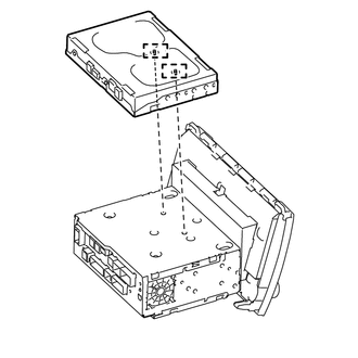
INSTALLATION PROCEDURE 1. INSTALL STEREO COMPONENT TUNER ASSEMBLY
2. INSTALL NO. 2 RADIO RECEIVER BRACKET (a) Install the No. 2 radio receiver bracket with the 5 bolts. Torque: 3.5 N·m {36 kgf·cm, 31 in·lbf} 3. INSTALL NO. 1 RADIO RECEIVER BRACKET (a) Install the No. 1 radio receiver bracket with the 5 bolts. Torque: 3.5 N·m {36 kgf·cm, 31 in·lbf} 4. INSTALL NO. 1 NAVIGATION WIRE (a) Connect each connector to install the No. 1 navigation wire. 5. INSTALL RADIO AND DISPLAY RECEIVER ASSEMBLY 6. INSTALL AIR CONDITIONING CONTROL ASSEMBLY 7. INSTALL CENTER LOWER INSTRUMENT COVER 8. CONNECT CABLE TO NEGATIVE BATTERY TERMINAL NOTICE: When disconnecting the cable, some systems need to be initialized after the cable is reconnected (See page
|
Toyota Tundra Service Manual > Sliding Roof System: Parts Location
PARTS LOCATION ILLUSTRATION *1 SLIDING ROOF DRIVE GEAR SUB-ASSEMBLY (SLIDING ROOF ECU) *2 ROOF CONSOLE BOX ASSEMBLY - SLIDING ROOF SWITCH *3 FRONT DOOR COURTESY LIGHT SWITCH LH *4 DRIVER SIDE JUNCTION BLOCK ASSEMBLY - S/ROOF FUSE - ECU-IG1 NO. 4 FUSE *5 MAIN BODY ECU (MULTIPLEX NETWORK BODY ECU) - - ...