Components COMPONENTS ILLUSTRATION 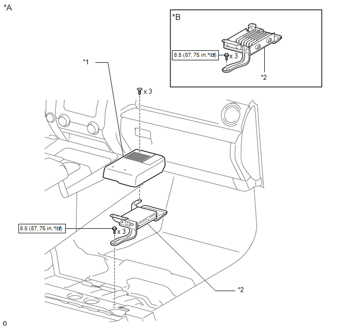
Installation INSTALLATION PROCEDURE 1. INSTALL STEREO COMPONENT AMPLIFIER ASSEMBLY 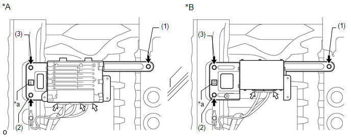
(a) Attach the guide to install the stereo component amplifier assembly. (b) Install the 3 bolts. Torque: 8.5 N·m {87 kgf·cm, 75 in·lbf} HINT: Tighten the bolts in the order shown in the illustration. (c) for 12 Speakers: Connect the 3 connectors. (d) except 12 Speakers: Connect the 2 connectors. 2. INSTALL AUDIO AMPLIFIER COVER (a) Attach the 3 clips to install the audio amplifier cover. 3. INSTALL FRONT SEAT ASSEMBLY RH (a) for Manual Seat: Click here
(b) for Power Seat: Click here
4. CONNECT CABLE TO NEGATIVE BATTERY TERMINAL NOTICE: When disconnecting the cable, some systems need to be initialized after the cable is reconnected. Click here Removal REMOVAL PROCEDURE 1. PRECAUTION NOTICE: After turning the ignition switch off, waiting time may be required before disconnecting the cable from the battery terminal. Therefore, make sure to read the disconnecting the cable from the battery terminal notice before proceeding with work. Click here 2. DISCONNECT CABLE FROM NEGATIVE BATTERY TERMINAL CAUTION: Wait at least 90 seconds after disconnecting the cable from the negative (-) battery terminal to disable the SRS system. NOTICE: When disconnecting the cable, some systems need to be initialized after the cable is reconnected. Click here 3. REMOVE FRONT SEAT ASSEMBLY RH (a) for Manual Seat: Click here (b) for Power Seat: Click here 4. REMOVE AUDIO AMPLIFIER COVER (a) Detach the 3 clips and remove the audio amplifier cover. 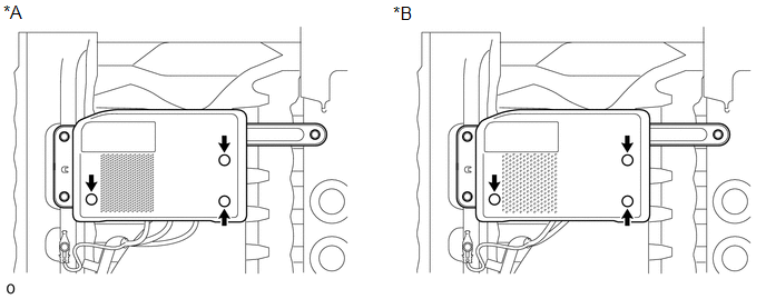
5. REMOVE STEREO COMPONENT AMPLIFIER ASSEMBLY 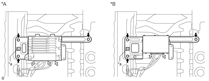
(a) for 12 Speakers: Disconnect the 3 connectors. (b) except 12 Speakers: Disconnect the 2 connectors. (c) Remove the 3 bolts. (d) Detach the guide and stereo component amplifier assembly. |
Toyota Tundra Service Manual > Wiper And Washer System: Washer Fluid Level Warning Switch Circuit
DESCRIPTION When the volume of washer fluid decreases below a certain level (when the washer fluid level warning switch is turned ON), the combination meter warns the driver through the warning message on the combination meter. WIRING DIAGRAM PROCEDURE 1. READ VALUE USING TECHSTREAM (WASHER FLUID LE ...


