Toyota Tundra Service Manual: Data Signal Circuit between Navigation Receiver Assembly and Stereo Jack Adapter

Toyota Tundra Service Manual / Audio, Visual, Telematics / Navigation / Multi Info Display / Navigation System / Data Signal Circuit between Navigation Receiver Assembly and Stereo Jack Adapter

DESCRIPTION

The No. 1 stereo jack adapter assembly sends the sound data signal or image data signal from a USB device to the navigation receiver assembly via this circuit.

WIRING DIAGRAM
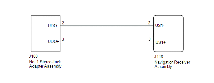
PROCEDURE

1.

CHECK HARNESS AND CONNECTOR (NAVIGATION RECEIVER ASSEMBLY - NO. 1 STEREO JACK ADAPTER ASSEMBLY)

(a) Disconnect the J116 navigation receiver assembly connector.

(b) Disconnect the J100 No. 1 stereo jack adapter assembly connector.

(c) Measure the resistance according to the value(s) in the table below.

Standard Resistance:

Tester Connection

Condition

Specified Condition

J116-2 (US1-) - J100-2 (UDO-)

Always

Below 1 Ω

J116-3 (US1+) - J100-3 (UDO+)

Always

Below 1 Ω

J116-2 (US1-) - Body ground

Always

10 kΩ or higher

J116-3 (US1+) - Body ground

Always

10 kΩ or higher

OK

PROCEED TO NEXT SUSPECTED AREA SHOWN IN PROBLEM SYMPTOMS TABLE

NG

REPAIR OR REPLACE HARNESS OR CONNECTOR

    Data Signal Circuit between Navigation Receiver Assembly and Extension Module

    Diagnostic Trouble Code Chart

    See More:

    Toyota Tundra Service Manual > Intuitive Parking Assist System: System Description
    SYSTEM DESCRIPTION 1. GENERAL (a) When the vehicle is driven at 10 km/h (6.2 mph) or less, the ultrasonic sensors detect any obstacles at the corners and rear of the vehicle. The system then informs the driver of the distance between the sensors and the obstacles as well as their positions by indica ...

    Toyota Tundra Owners Manual

    Toyota Tundra Service Manual

    © 2025 Copyright www.ttundra.com
    0.0112