DESCRIPTION The stereo component tuner assembly sends the sound data signal or image data signal from a device to the navigation receiver assembly via this circuit. WIRING DIAGRAM 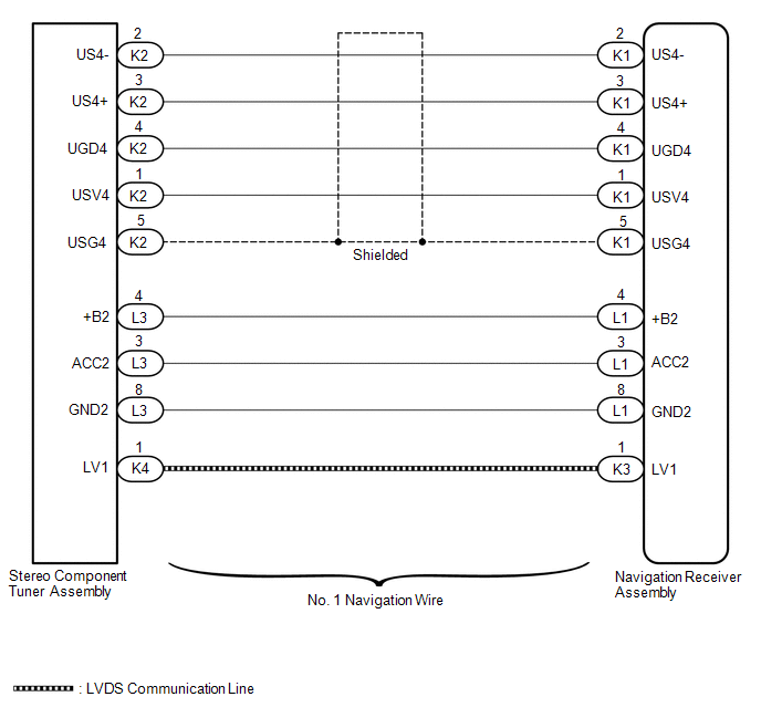 CAUTION / NOTICE / HINT NOTICE: After replacing the stereo component tuner assembly of vehicles subscribed to pay-type satellite radio broadcasts, XM radio ID registration is necessary. PROCEDURE
(a) Disconnect the K1 and L1 navigation receiver assembly connectors. (b) Disconnect the K2 and L3 stereo component tuner assembly connector. (c) Measure the resistance according to the value(s) in the table below. Standard Resistance:
(a) Replace the No. 1 navigation wire with a known good one. for Column Shift Type: See page for Floor Shift Type: See page
(b) Check that the malfunction disappears. OK: Malfunction disappears.
|
Toyota Tundra Service Manual > Front Power Seat Control System(w/ Memory): Slide Sensor Malfunction (B2650)
DESCRIPTION When the position control ECU and switch assembly does not receive a sensor signal despite forward or rearward movement of the seat by power seat motor operation, this DTC is stored. DTC Code DTC Detection Condition Trouble Area B2650 The forward and rearward lock detection position of t ...


