DESCRIPTION This circuit is used when the voice guidance in the navigation system is on or an incoming cellular phone voice in the "Bluetooth" hands-free system is heard. Using this circuit, the navigation receiver assembly sends the signals to the stereo component amplifier assembly. WIRING DIAGRAM 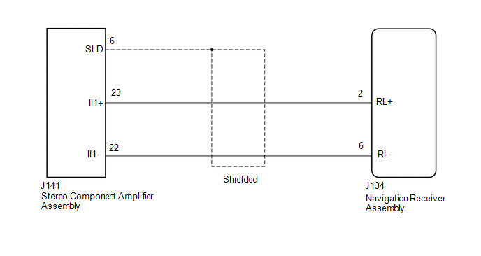 PROCEDURE
(a) Disconnect the J134 navigation receiver assembly connector. (b) Disconnect the J141 stereo component amplifier connector. (c) Measure the resistance according to the value(s) in the table below. Standard Resistance:
|
Toyota Tundra Service Manual > Sfi System: Secondary Air Injection System Pump Stuck On Bank1 (P2444-P2447)
DESCRIPTION Refer to P2440 (See page ). DTC No. DTC Detection Condition Trouble Area P2444 P2446 Secondary air pressure more than 3.0 kPa (23 mmHg) despite ECM commanding air pump to turn off (2 trip detection logic) Short in air pump circuit Open or short in pressure sensor circuit Pressure sensor ...


