Toyota Tundra Service Manual: Navigation Receiver Assembly Power Source Circuit

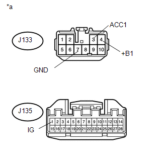
DESCRIPTION

This circuit provides power to the navigation receiver assembly.

WIRING DIAGRAM

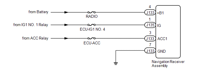
CAUTION / NOTICE / HINT

NOTICE:

Inspect the fuses for circuits related to this system before performing the following inspection procedure.

PROCEDURE

1.

CHECK HARNESS AND CONNECTOR (NAVIGATION RECEIVER ASSEMBLY - BATTERY AND BODY GROUND)

(a) Disconnect the navigation receiver assembly connectors.

(b) Measure the resistance according to the value(s) in the table below.

Standard Resistance:

Tester Connection

Condition

Specified Condition

J133-7 (GND) - Body ground

Always

Below 1 Ω

(c) Measure the voltage according to the value(s) in the table below.

Standard Voltage:

Tester Connection

Condition

Specified Condition

J133-4 (+B1) - Body ground

Always

11 to 14 V

J133-3 (ACC1) - Body ground

Ignition switch ACC

11 to 14 V

J135-1 (IG) - Body ground

Ignition switch ON

11 to 14 V

Text in Illustration

*a

Front view of wire harness connector

(to Navigation Receiver Assembly)

OK

PROCEED TO NEXT SUSPECTED AREA SHOWN IN PROBLEM SYMPTOMS TABLE

NG

REPAIR OR REPLACE HARNESS OR CONNECTOR

    Mute Signal Circuit between Navigation Receiver Assembly and Stereo Component Amplifier

    Navigation Voice Circuit

    See More:

    Toyota Tundra Service Manual > Instrument Panel Speaker(for Crewmax): Installation
    INSTALLATION PROCEDURE 1. INSTALL FRONT NO. 4 SPEAKER ASSEMBLY (for 12 Speakers) (a) Connect the connector. (b) Temporarily install the front No. 4 speaker assembly by aligning the positioning pins of the front No. 4 speaker assembly with the instrument panel. (c) Install the front No. 4 speaker ass ...

    Toyota Tundra Owners Manual

    Toyota Tundra Service Manual

    © 2026 Copyright www.ttundra.com
    0.0266