DESCRIPTION The navigation receiver assembly sends a sound signal to the stereo component amplifier assembly via this circuit. The sound signal that has been sent is amplified by the stereo component amplifier assembly, and then is sent to the speakers. WIRING DIAGRAM 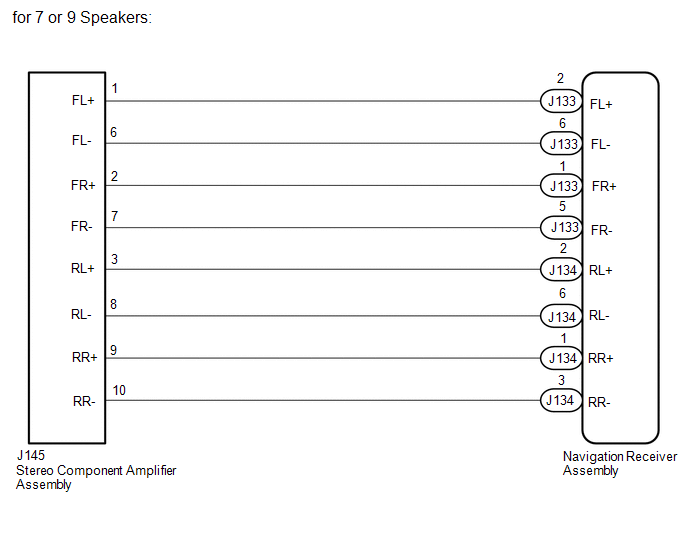
 PROCEDURE
(a) for 7 or 9 Speakers: (1) Disconnect the J134 and J133 navigation receiver assembly connectors. (2) Disconnect the J145 stereo component amplifier assembly connector. (3) Measure the resistance according to the value(s) in the table below. Standard Resistance:
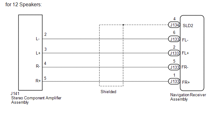
(b) for 12 Speakers: (1) Disconnect the J134 and J133 navigation receiver assembly connectors. (2) Disconnect the J141 stereo component amplifier assembly connector. (3) Measure the resistance according to the value(s) in the table below. Standard Resistance:
|
Toyota Tundra Service Manual > Power Window Control System(w/ Jam Protection Function): Data List / Active Test
DATA LIST / ACTIVE TEST 1. READ DATA LIST HINT: Using the Techstream to read the Data List allows the values or states of switches, sensors, actuators and other items to be read without removing any parts. This non-intrusive inspection can be very useful because intermittent conditions or signals ma ...


