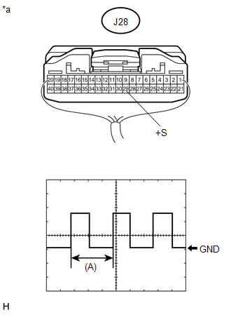
DESCRIPTION The navigation receiver assembly receives a vehicle speed signal from the combination meter assembly to control the ASL function. HINT:
WIRING DIAGRAM 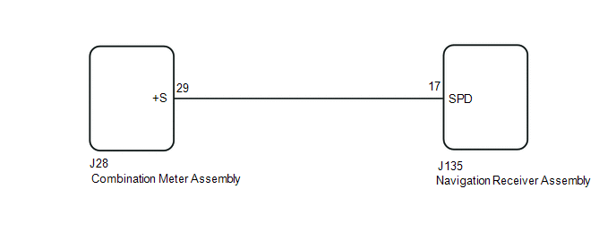 PROCEDURE
(a) Disconnect the J135 navigation receiver assembly connector. (b) Disconnect the J28 combination meter assembly connector. (c) Measure the resistance according to the value(s) in the table below. Standard Resistance:
|
Toyota Tundra Service Manual > Sfi System: Camshaft Position "B" Actuator Circuit / Open (Bank 1) (P0013,P0023)
DESCRIPTION This DTC is designed to detect opens or shorts in the camshaft oil control valve (OCV) circuit. If the OCV's duty-cycle is excessively high or low while the engine is running, the ECM will illuminate the MIL and store the DTC. The VVT (variable valve timing) system adjusts the intake and ...