INSTALLATION CAUTION / NOTICE / HINT NOTICE:
HINT:
PROCEDURE 1. INSTALL BLIND SPOT MONITOR BRACKET LH
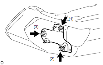
2. INSTALL BLIND SPOT MONITOR BRACKET RH HINT: Use the same procedure described for the LH side. 3. INSTALL BLIND SPOT MONITOR SENSOR LH (a) Install the blind spot monitor sensor LH with the 3 nuts. Torque: 9.0 N·m {92 kgf·cm, 80 in·lbf} 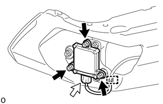 Text in Illustration Text in Illustration
(b) Attach the wire harness clamp and connect the connector. 4. INSTALL BLIND SPOT MONITOR SENSOR RH HINT: Use the same procedure described for the LH side. 5. PERFORM BLIND SPOT MONITOR SENSOR INSTALLATION CONDITION INSPECTION Click here 6. INSTALL REAR BUMPER EXTENSION INSERT LH Click here 7. INSTALL REAR BUMPER EXTENSION INSERT RH Click here 8. INSTALL REAR BUMPER PAD SUB-ASSEMBLY LH Click here 9. INSTALL REAR BUMPER PLATE LH Click here 10. INSTALL REAR BUMPER PLATE RH Click here 11. INSTALL REAR BUMPER COVER Click here 12. PERFORM BLIND SPOT MONITOR BEAM AXIS INSPECTION Click here 13. PERFORM DIAGNOSTIC SYSTEM CHECK Click here |
Toyota Tundra Service Manual > Vehicle Stability Control System: ABS Warning Light does not Come ON
DESCRIPTION The skid control ECU (brake actuator assembly) is connected to the combination meter assembly via CAN communication. CAUTION / NOTICE / HINT NOTICE: When replacing the skid control ECU (brake actuator assembly), perform system variant learning and acceleration sensor zero point calibrati ...