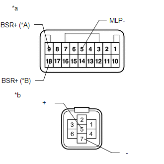
DESCRIPTION This DTC is stored when the blind spot monitor sensor RH detects an open in the outer rear view mirror indicator RH.
WIRING DIAGRAM 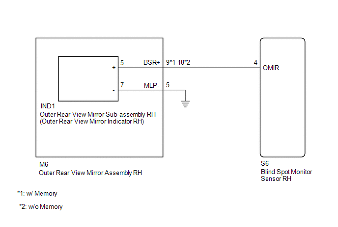 CAUTION / NOTICE / HINT NOTICE: When checking for DTCs, make sure that the blind spot monitor system is turned on. PROCEDURE
(a) Clear the DTCs. Click here
(b) Recheck for DTCs and check if the same DTC is output again. Click here OK: No DTCs are output.
(a) Disconnect the S6 blind spot monitor sensor RH connector. (b) Disconnect the M6 outer rear view mirror assembly RH connector. (c) Measure the resistance according to the value(s) in the table below. Standard Resistance: w/ Memory
(b) Disconnect the IND1 outer rear view mirror sub-assembly RH connector. (c) Measure the resistance according to the value(s) in the table below. Standard Resistance: w/ Memory
(a) Remove the outer rear view mirror sub-assembly RH. Click here
(b) Inspect the outer rear view mirror indicator RH on the outer rear view mirror sub-assembly RH. Click here
|
Toyota Tundra Owners Manual > Before driving: Trailer towing
Your vehicle is designed primarily as a passenger-and-load-carrying vehicle. Towing a trailer can have an adverse impact on handling, performance, braking, durability, and fuel consumption. For your safety and the safety of others, you must not overload your vehicle or trailer. You must also ensure ...