DESCRIPTION This DTC is stored when the blind spot monitor sensor LH detects an open in the outer rear view mirror indicator LH.
WIRING DIAGRAM 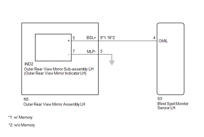 CAUTION / NOTICE / HINT NOTICE: When checking for DTCs, make sure that the blind spot monitor system is turned on. PROCEDURE
(a) Clear the DTCs. Click here
(b) Recheck for DTCs and check if the same DTC is output again. Click here OK: No DTCs are output.
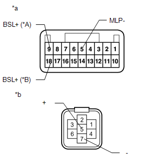
(a) Disconnect the S5 blind spot monitor sensor LH connector. (b) Disconnect the N5 outer rear view mirror assembly LH connector. (c) Measure the resistance according to the value(s) in the table below. Standard Resistance: w/ Memory
(b) Disconnect the IND2 outer rear view mirror sub-assembly LH connector. (c) Measure the resistance according to the value(s) in the table below. Standard Resistance: w/ Memory
(a) Remove the outer rear view mirror sub-assembly LH. Click here
(b) Inspect the outer rear view mirror indicator LH on the outer rear view mirror sub-assembly LH. Click here
|
Toyota Tundra Service Manual > Air Conditioning System(for Automatic Air Conditioning System): Air Outlet Damper Control Servo Motor Circuit (B1443/43)
DESCRIPTION The No. 1 damper servo sub-assembly (air outlet servo motor) sends pulse signals to inform the air conditioning amplifier of the damper position. The air conditioning amplifier activates the motor (normal, reverse) based on the signals to move the air outlet damper to any position, which ...