DESCRIPTION The No. 3 ultrasonic sensor sends and receives ultrasonic waves. Based on the received wave, the sensor calculates the approximate distance value between the vehicle and the obstacle, and sends the distance value as a signal to the clearance warning ECU assembly. WIRING DIAGRAM 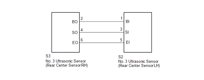 PROCEDURE
(a) Remove the No. 3 ultrasonic sensor (rear center sensor LH) (See page
(b) Inspect the No. 3 ultrasonic sensor (rear center sensor LH) (See page
(a) Disconnect the S2 No. 3 ultrasonic sensor (rear center sensor LH) connector. (b) Disconnect the S3 No. 3 ultrasonic sensor (rear center sensor RH) connector. (c) Measure the Resistance according to the value(s) in the table below. Standard Resistance:
|
Toyota Tundra Service Manual > Key Reminder Warning System: Customize Parameters
CUSTOMIZE PARAMETERS CUSTOMIZE KEY REMINDER WARNING SYSTEM (a) Customizing with the Techstream (1) Connect the Techstream to the DLC3. (2) Turn the ignition switch to ON. (3) Turn the Techstream on. (4) Enter the following menus: Customize / Warning. (5) Select the setting by referring to the table ...

 ).
).


