DESCRIPTION The No. 3 ultrasonic sensor sends and receives ultrasonic waves. Based on the received wave, the sensor calculates the approximate distance value between the vehicle and the obstacle, and sends the distance value as a signal to the clearance warning ECU assembly. WIRING DIAGRAM 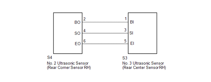 PROCEDURE
(a) Replace the No. 3 ultrasonic sensor (rear center sensor RH) (See page
(b) Inspect the No. 3 ultrasonic sensor (rear center sensor RH) (See page
(a) Disconnect the S3 No. 3 ultrasonic sensor (rear center sensor RH) connector. (b) Disconnect the S4 No. 2 ultrasonic sensor (rear corner sensor RH) connector. (c) Measure the resistance according to the value(s) in the table below. Standard Resistance:
|
Toyota Tundra Service Manual > Hazard Warning Switch: Inspection
INSPECTION PROCEDURE 1. INSPECT AIR CONDITIONING CONTROL ASSEMBLY (HAZARD WARNING SWITCH) (a) Measure the resistance according to the value(s) in the table below. Standard Resistance: Tester Connection Switch Condition Specified Condition 1 (HAZ) - 5 (GND) Hazard warning switch off 10 kΩ or higher ...

 ).
).


