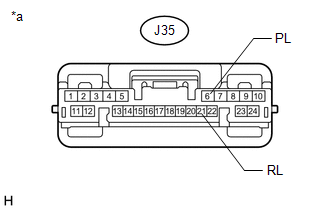
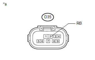
DESCRIPTION This circuit sends the park/neutral position switch assembly signals to the clearance warning ECU assembly. WIRING DIAGRAM
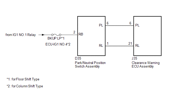
CAUTION / NOTICE / HINT
NOTICE: Inspect the fuses for circuits related to this system before performing the following procedure. PROCEDURE
| 1. |
CHECK CLEARANCE WARNING ECU ASSEMBLY |
| (a) Disconnect the clearance warning ECU assembly connector. |
|
(b) Measure the voltage according to the value(s) in the table below. Standard Voltage: |
Tester Connection | Switch Condition |
Specified Condition | |
J35-6 (PL) - Body ground |
Ignition switch ON, shift lever in P |
11 to 14 V | |
Ignition switch ON, shift lever not in P |
Below 1 V | |
J35-21 (RL) - Body ground |
Ignition switch ON, shift lever in R |
11 to 14 V | |
Ignition switch ON, shift lever not in R |
Below 1 V | Text in Illustration |
*a | Front view of wire harness connector
(to Clearance Warning ECU Assembly) |
| OK |
| PROCEED TO NEXT SUSPECTED AREA SHOWN IN PROBLEM SYMPTOMS TABLE |
|
NG |
| |
| 2. |
CHECK HARNESS AND CONNECTOR (PARK/NEUTRAL POSITION SWITCH ASSEMBLY - CLEARANCE WARNING ECU ASSEMBLY) |
(a) Disconnect the D35 park/neutral position switch assembly connector.
(b) Disconnect the J35 clearance warning ECU assembly connector. (c) Measure the resistance according to the value(s) in the table below.
Standard Resistance: |
Tester Connection | Condition |
Specified Condition | |
D35-6 (PL) - J35-6 (PL) |
Always | Below 1 Ω | |
D35-1 (RL) - J35-21 (RL) |
Always | Below 1 Ω | |
D35-6 (PL) - Body ground |
Always | 10 kΩ or higher | |
D35-1 (RL) - Body ground |
Always | 10 kΩ or higher |
| NG |
| REPAIR OR REPLACE HARNESS OR CONNECTOR |
|
OK |
| |
| 3. |
CHECK HARNESS AND CONNECTOR (PARK/NEUTRAL POSITION SWITCH ASSEMBLY - BATTERY) |
| (a) Disconnect the park/neutral position switch assembly connector. |
|
(b) Measure the voltage according to the value(s) in the table below. Standard Voltage: |
Tester Connection | Switch Condition |
Specified Condition | |
D35-2 (RB) - Body ground |
Ignition switch ON | 11 to 14 V | Text in Illustration |
*a | Front view of wire harness connector
(to Park/Neutral Position Switch Assembly) |
HINT: *: Park/neutral position switch assembly replacement procedure:
- for A760E: See page
- for A760F: See page
- for AB60E: See page
- for AB60F: See page
| OK |
| REPLACE PARK/NEUTRAL POSITION SWITCH ASSEMBLY* |
| NG |
| REPAIR OR REPLACE HARNESS OR CONNECTOR | |