Toyota Tundra Service Manual: Parts Location

PARTS LOCATION

ILLUSTRATION
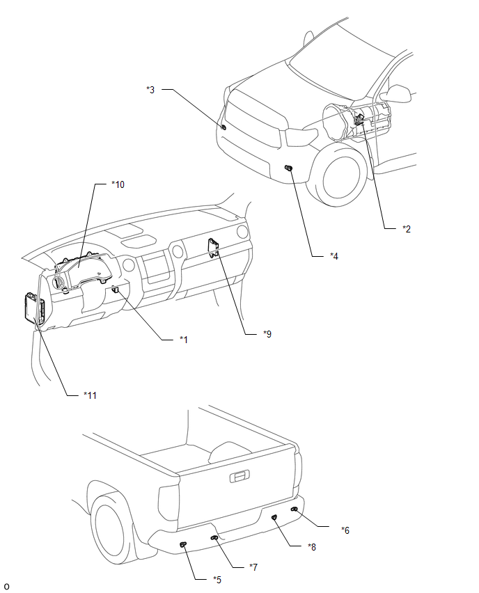
*1

BACK SONAR OR CLEARANCE SONAR SWITCH ASSEMBLY

*2

PARK/NEUTRAL POSITION SWITCH ASSEMBLY

*3

NO. 1 ULTRASONIC SENSOR (FRONT CORNER SENSOR RH)

*4

NO. 1 ULTRASONIC SENSOR (FRONT CORNER SENSOR LH)

*5

NO. 2 ULTRASONIC SENSOR (FRONT CORNER SENSOR LH)

*6

NO. 2 ULTRASONIC SENSOR (REAR CORNER SENSOR RH)

*7

NO. 3 ULTRASONIC SENSOR (REAR CENTER SENSOR LH)

*8

NO. 3 ULTRASONIC SENSOR (REAR CENTER SENSOR RH)

*9

CLEARANCE WARNING ECU ASSEMBLY

*10

COMBINATION METER ASSEMBLY

*11

COWL SIDE JUNCTION BLOCK LH

- ECU-IG1 NO.4 FUSE

- BKUP LP FUSE (for Floor Shift Type)

-

-

    Park / Neutral Position Switch Circuit

    Precaution

    See More:

    Toyota Tundra Service Manual > Can Communication System: Open in Bus 3 Main Bus Line
    DESCRIPTION There may be an open circuit in one of the CAN main bus lines when the resistance between terminals 6 (CA3H) and 21 (CA3L) or 19 (CAYH) and 20 (CAYL) of the central gateway ECU (network gateway ECU) is 70 Ω or higher. Symptom Trouble Area Resistance between terminals 6 (CA3H) and 21 (CA ...

    Toyota Tundra Owners Manual

    Toyota Tundra Service Manual

    © 2026 Copyright www.ttundra.com
    0.0347