DESCRIPTION The No. 2 ultrasonic sensor sends and receives ultrasonic waves. Based on the received wave, the sensor calculates the approximate distance value between the vehicle and the obstacle, and sends the distance value as a signal to the clearance warning ECU assembly. WIRING DIAGRAM 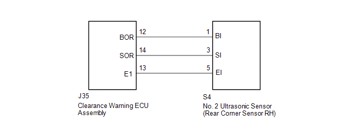 PROCEDURE
(a) Remove the No. 2 ultrasonic sensor (rear corner sensor RH) (See page
(b) Inspect the No. 2 ultrasonic sensor (rear corner sensor RH) (See page
(a) Disconnect the S4 No. 2 ultrasonic sensor (rear corner sensor RH) connector. (b) Disconnect the J35 clearance warning ECU assembly connector. (c) Measure the resistance according to the value(s) in the table below. Standard Resistance:
|
Toyota Tundra Service Manual > Sfi System: Engine Coolant Temperature Circuit Malfunction (P0115,P0117,P0118)
DESCRIPTION A thermistor, whose resistance value varies according to the ECT, is built into the Engine Coolant Temperature (ECT) sensor. The structure of the sensor and its connection to the ECM are the same as those of the Intake Air Temperature (IAT) sensor. HINT: When DTC P0115, P0117 or P0118 is ...

 ).
).


