REMOVAL PROCEDURE 1. REMOVE LUGGAGE COMPARTMENT SIDE COVER SUB-ASSEMBLY LH 2. REMOVE LUGGAGE COMPARTMENT SIDE COVER SUB-ASSEMBLY RH 3. REMOVE SEAT FLOOR BOX
4. REMOVE REAR SEAT ASSEMBLY
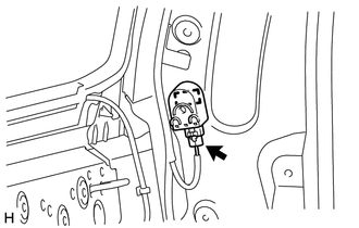
5. REMOVE REAR DOOR SCUFF PLATE LH 6. REMOVE REAR DOOR OPENING TRIM WEATHERSTRIP LH 7. REMOVE LOWER QUARTER TRIM PANEL ASSEMBLY LH 8. REMOVE FRONT QUARTER TRIM PANEL ASSEMBLY LH 9. REMOVE BLIND SPOT MONITOR BUZZER
(b) Detach the clamp and remove the blind spot monitor buzzer. |
Toyota Tundra Service Manual > 1ur-fe Engine Control: Vvt Sensor
ComponentsCOMPONENTS ILLUSTRATION InstallationINSTALLATION PROCEDURE 1. INSTALL VVT SENSOR (a) Install the 4 sensors with the 4 bolts. Torque: 10 N·m {102 kgf·cm, 7 ft·lbf} (b) Connect the 4 sensor connectors. 2. INSTALL AIR CLEANER HOSE ASSEMBLY 3. INSTALL V-BANK COVER SUB-ASSEMBLY RemovalREMOV ...