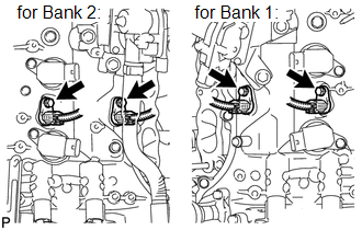
Components COMPONENTS ILLUSTRATION 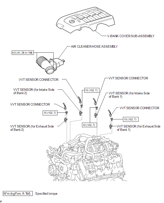 Installation INSTALLATION PROCEDURE 1. INSTALL VVT SENSOR
(b) Connect the 4 sensor connectors. 2. INSTALL AIR CLEANER HOSE ASSEMBLY 3. INSTALL V-BANK COVER SUB-ASSEMBLY Removal REMOVAL PROCEDURE 1. REMOVE V-BANK COVER SUB-ASSEMBLY 2. REMOVE AIR CLEANER HOSE ASSEMBLY 3. REMOVE VVT SENSOR
(b) Remove the 4 bolts and 4 sensors. |
Toyota Tundra Service Manual > Starter(for 2.0 Kw Type): Reassembly
REASSEMBLY PROCEDURE 1. INSTALL STARTER CENTER BEARING CLUTCH SUB-ASSEMBLY (a) Apply high-temperature grease to the areas of the starter pinion drive lever indicated in the illustration. (b) Install the starter pinion drive lever and rubber seal to the starter center bearing clutch. (c) Install the ...