TERMINALS OF ECU 1. CHECK RADIO AND DISPLAY RECEIVER ASSEMBLY 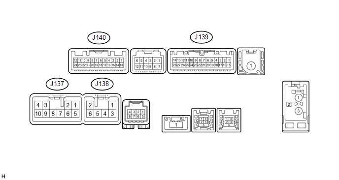 (a) Disconnect the J137 and J139 radio and display receiver assembly connectors. (b) Measure the voltage and resistance according to the value(s) in the table below.
(c) Reconnect the J137 and J139 radio and display receiver assembly connectors. (d) Measure the voltage and waveform according to the value(s) in the table below.
(e) Using an oscilloscope, check the waveform. 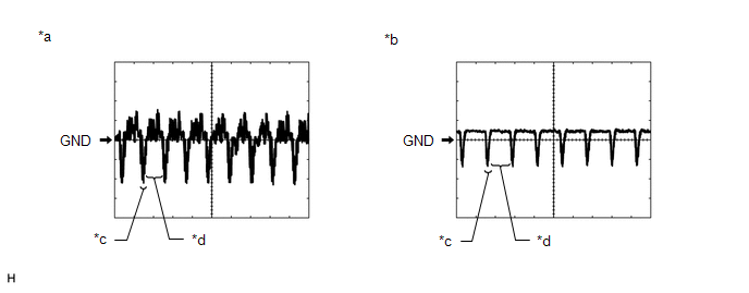
(1) Waveform 1 Measurement Condition
HINT: The video waveform changes according to the image sent by the television camera assembly. (2) Waveform 2 Measurement Condition
HINT: The video waveform changes according to the image sent by the television camera assembly. |
Toyota Tundra Service Manual > Automatic Transmission System: Shift Solenoid "E" Control Circuit Low (Shift Solenoid Valve SR) (P0985,P0986)
DESCRIPTION Shifting from 1st to 6th is performed in combination with ON and OFF operation of the shift solenoid valves SL1, SL2, S1, S2, S3, S4 and SR, which are controlled by the ECM. If an open or short circuit occurs in any of the shift solenoid valves, the ECM controls the remaining normal shif ...


