Components COMPONENTS ILLUSTRATION 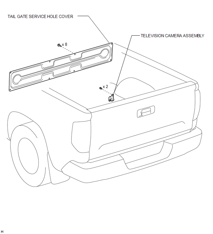 Installation INSTALLATION CAUTION / NOTICE / HINT HINT: A bolt without a torque specification is shown in the standard bolt chart (see page
PROCEDURE 1. INSTALL TELEVISION CAMERA ASSEMBLY (a) Install the television camera assembly with the 2 bolts. (b) Connect the television camera connector. 2. INSTALL TAIL GATE SERVICE HOLE COVER
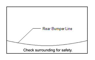
3. CHECK TELEVISION CAMERA ASSEMBLY ANGLE
Removal REMOVAL PROCEDURE 1. REMOVE TAIL GATE SERVICE HOLE COVER
2. REMOVE TELEVISION CAMERA ASSEMBLY 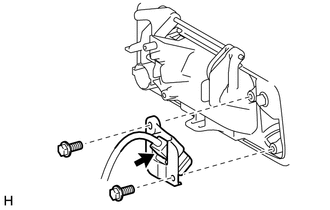 (a) Disconnect the television camera connector. (b) Remove the 2 bolts and television camera assembly. |
Toyota Tundra Service Manual > Steering Column Assembly(for Manual Tilt And Manual Telescopic Steering Column): Components
COMPONENTS ILLUSTRATION *1 COWL SIDE TRIM BOARD LH *2 FRONT DOOR SCUFF PLATE LH *3 INSTRUMENT SIDE PANEL LH *4 LOWER INSTRUMENT PANEL FINISH PANEL SUB-ASSEMBLY LH *5 LOWER NO. 1 INSTRUMENT PANEL AIRBAG ASSEMBLY *6 NO. 3 AIR DUCT SUB-ASSEMBLY *7 HOOD LOCK CONTROL LEVER - - N*m (kgf*cm, ft.*lbf): Spec ...

 ).
).