Toyota Tundra Service Manual: Removal

REMOVAL

PROCEDURE

1. REMOVE RADIATOR GRILLE SUB-ASSEMBLY

Click here

2. REMOVE FRONT BUMPER COVER

Click here

3. REMOVE NO. 1 ULTRASONIC SENSOR RETAINER (for Steel Type Bumper)

(a) Remove the No. 1 ultrasonic sensor retainer as shown in the illustration.

HINT:

The illustration shows the No. 1 ultrasonic sensor retainer for the LH. The horizontal orientation of the No. 1 ultrasonic sensor retainer for the RH is opposite that of the image shown in the illustration.

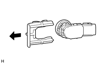
4. REMOVE NO. 1 ULTRASONIC SENSOR (for Steel Type Bumper)

(a) Remove the No. 1 ultrasonic sensor as shown in the illustration.

HINT:

The illustration shows the No. 1 ultrasonic sensor for the LH. The horizontal orientation of the No. 1 ultrasonic sensor for the RH is opposite that of the image shown in the illustration.

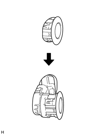
5. REMOVE NO. 1 ULTRASONIC SENSOR (for Resin Type Bumper)

(a) Detach the 4 claws and remove the No. 1 ultrasonic sensor as shown in the illustration.

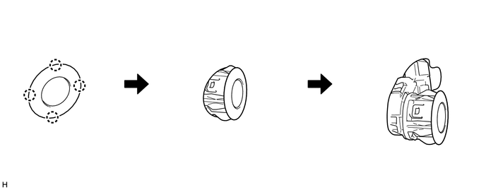
HINT:

The illustration shows the No. 1 ultrasonic sensor for the RH. The horizontal orientation of the No. 1 ultrasonic sensor for the LH is opposite that of the image shown in the illustration.

    Installation

    Ultrasonic Sensor(for Rear Side)

    See More:

    Toyota Tundra Service Manual > Sfi System: Oxygen (A/F) Sensor Signal Stuck Lean (Bank 1 Sensor 1) (P2195-P2198)
    DESCRIPTION The A/F sensor generates a voltage* that corresponds to the actual air-fuel ratio. This sensor voltage is used to provide the ECM with feedback so that it can control the air-fuel ratio. The ECM determines the deviation from the stoichiometric air-fuel ratio, and regulates the fuel injec ...

    Toyota Tundra Owners Manual

    Toyota Tundra Service Manual

    © 2026 Copyright www.ttundra.com
    0.0336