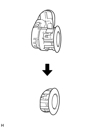
INSTALLATION PROCEDURE 1. INSTALL NO. 1 ULTRASONIC SENSOR (for Steel Type Bumper)
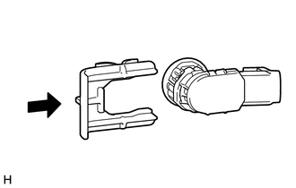
2. INSTALL NO. 1 ULTRASONIC SENSOR RETAINER (for Steel Type Bumper)
3. INSTALL NO. 1 ULTRASONIC SENSOR (for Resin Type Bumper) 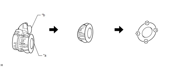 (a) Attach the 4 claws to install the No. 1 ultrasonic sensor as shown in the illustration. Text in Illustration
NOTICE:
4. INSTALL FRONT BUMPER COVER Click here
5. INSTALL RADIATOR GRILLE SUB-ASSEMBLY Click here 6. ADJUST FOG LIGHT AIMING (a) for Halogen Fog Light: Click here (b) for LED Fog Light: Click here |
Toyota Tundra Service Manual > Can Communication System: Lost Communication with "Door Control Module A" (U0199)
DESCRIPTION DTC No. DTC Detection Condition Trouble Area U0199 There is no communication from the outer mirror control ECU assembly LH. Outer mirror control ECU assembly LH CAN branch wire or connector Power source or inside of outer mirror control ECU assembly LH Outer mirror control ECU assembly L ...