Toyota Tundra Service Manual: Installation

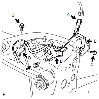
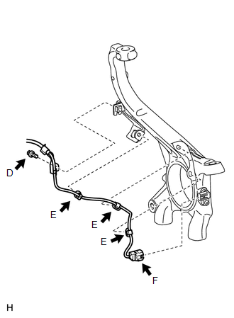
INSTALLATION

PROCEDURE

1. INSTALL FRONT SKID CONTROL SENSOR CLAMP LH

(a) Install the skid control sensor clamp (labeled A) with the bolt (labeled B).

Torque:

13 N·m {127 kgf·cm, 9 ft·lbf}

NOTICE:

Install the bracket so that the rotation stopper (labeled C) touches the knuckle.

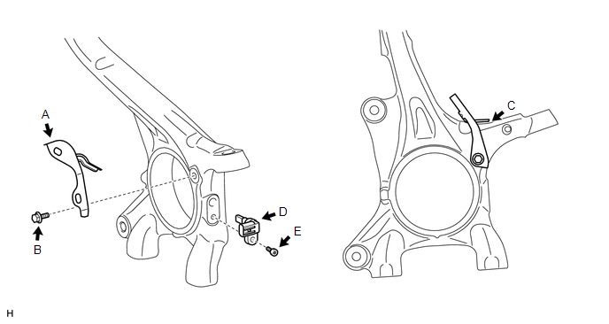
2. INSTALL FRONT SPEED SENSOR LH

(a) Install the speed sensor (labeled D) with the hexagon socket head cap bolt (labeled E).

Torque:

11 N·m {107 kgf·cm, 8 ft·lbf}

NOTICE:

  • Make sure there are no pieces of iron or other foreign matter attached to the sensor tip part.
  • While inserting the speed sensor into the knuckle hole, do not strike or damage the sensor tip part.
  • After installing the speed sensor, make sure there is no clearance or foreign matter between the sensor stay part and the knuckle.
  • Make sure there is no foreign matter attached to the magnetic rotor.

3. INSTALL FRONT SKID CONTROL SENSOR WIRE LH

(a) Connect the connector (labeled A).

(b) Install the 3 harness clamps (labeled B) with the 3 bolts (labeled C).

Torque:

13 N·m {127 kgf·cm, 9 ft·lbf}

NOTICE:

  • When installing the clamps, do not twist the wire harness.
  • For clamps with rotation stoppers, make sure the rotation stopper touches the installation position.

(c) Install the harness clamp with the bolt (labeled D).

Torque:

13 N·m {127 kgf·cm, 9 ft·lbf}

NOTICE:

  • When installing the clamp, do not twist the wire harness.
  • Make sure the clamp's rotation stopper touches the installation position.

(d) Attach the 3 clips (labeled E).

NOTICE:

  • When installing the clips, do not twist the wire harness.
  • When installing the clips, securely insert them as shown in the illustration.

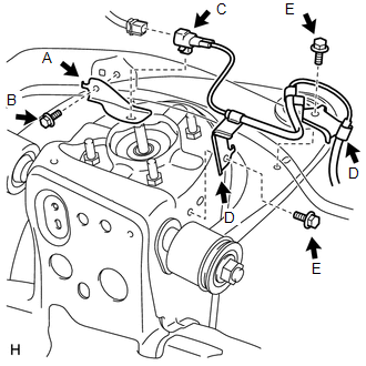
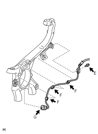
(e) Connect the speed sensor connector (labeled F).

NOTICE:

Securely connect the connector.

4. INSTALL FRONT SKID CONTROL SENSOR CLAMP RH

(a) Install the skid control sensor clamp (labeled A) with the bolt (labeled B).

Torque:

13 N·m {127 kgf·cm, 9 ft·lbf}

NOTICE:

Install the bracket so that the rotation stopper (labeled C) touches the knuckle.

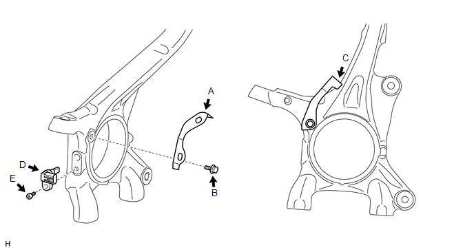
5. INSTALL FRONT SPEED SENSOR RH

(a) Install the speed sensor (labeled D) with the hexagon socket head cap bolt (labeled E).

Torque:

11 N·m {107 kgf·cm, 8 ft·lbf}

NOTICE:

  • Make sure there are no pieces of iron or other foreign matter attached to the sensor tip part.
  • While inserting the speed sensor into the knuckle hole, do not strike or damage the sensor tip part.
  • After installing the speed sensor, make sure there is no clearance or foreign matter between the sensor stay part and the knuckle.
  • Make sure there is no foreign matter attached to the magnetic rotor.

6. INSTALL FRONT SKID CONTROL SENSOR WIRE RH

(a) Install the skid control sensor clamp (labeled A) with the bolt (labeled B).

Torque:

for Bolt B :

8.0 N·m {82 kgf·cm, 71 in·lbf}

(b) Install the connector (labeled C) with connect the connector (labeled C).

(c) Install the 2 harness clamps (labeled D) with the 2 bolts (labeled E).

Torque:

for Bolt E :

13 N·m {127 kgf·cm, 9 ft·lbf}

NOTICE:

  • When installing the clamps, do not twist the wire harness.
  • For clamps with rotation stoppers, make sure the rotation stopper touches the installation position.

(d) Install the harness clamp with the bolt (labeled E).

Torque:

13 N·m {127 kgf·cm, 9 ft·lbf}

NOTICE:

  • When installing the clamp, do not twist the wire harness.
  • Make sure the clamp's rotation stopper touches the installation position.

(e) Attach the 3 clips (labeled F).

NOTICE:

  • When installing the clips, do not twist the wire harness.
  • When installing the clips, securely insert them as shown in the illustration.

(f) Connect the speed sensor connector (labeled G).

NOTICE:

Securely connect the connector.

7. INSTALL FRONT WHEEL

Torque:

for Aluminum Wheel :

131 N·m {1336 kgf·cm, 97 ft·lbf}

for Steel Wheel :

209 N·m {2131 kgf·cm, 154 ft·lbf}

8. CONNECT CABLE TO NEGATIVE BATTERY TERMINAL

9. CHECK SPEED SENSOR SIGNAL

(a) Check the speed sensor signal (See page ).

    Components

    Removal

    See More:

    Toyota Tundra Service Manual > Sfi System: Evaporative Emission Control System Incorrect Purge Flow (P0441)
    DTC SUMMARY DTC No. Monitoring Item Malfunction Detection Condition Trouble Area Detection Timing Detection Logic P0441 Purge VSV (Vacuum Switching Valve) stuck open Leak detection pump creates negative pressure (vacuum) in EVAP system and EVAP system pressure measured. Reference pressure measured a ...

    Toyota Tundra Owners Manual

    Toyota Tundra Service Manual

    © 2023 Copyright www.ttundra.com
    0.0045