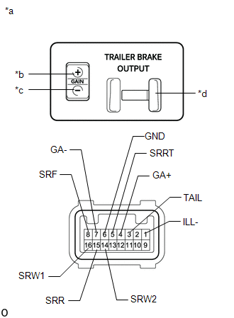
INSPECTION
PROCEDURE
1. INSPECT TRAILER BRAKE CONTROL SWITCH
(a) Measure the resistance according to the value(s) in the table below.
Standard Resistance:
Tester Connection
Switch Condition
Specified Condition
8 (SRF) -5 (SRRT)
-
2 kΩ to 3.09 kΩ
8 (SRF) -16 (SRW1)
Manual trailer brake output slider operated to maximum position (100%)
Below 1 kΩ
Manual trailer brake output slider not operated (0%)
2 kΩ to 3 kΩ
8 (SRF) -14 (SRW2)
8 (SRF) -15 (SRR)
12 Ω to 14 Ω
4 (GA+) -6 (GND)
GAIN (+) selection button pressed
Below 20 Ω
GAIN (+) selection button not pressed
100 kΩ or higher
4 (GA-) -6 (GND)
GAIN (-) selection button pressed
GAIN (-) selection button not pressed
If the result is not as specified, replace the trailer brake control switch.
*a
Component without harness connected
(Trailer brake control switch)
*b
GAIN (+) selection button
*c
GAIN (-) selection button
*d
Manual trailer brake output slider
(b) Check that the LED illuminates.
(1) Apply battery voltage between the terminals of the trailer brake control switch, and check the illumination condition.
OK:
Measurement Condition
Battery positive (+) →3 (TAIL)
Battery negative (-) → 1 (ILL-)
Illuminates
Indicator
Toyota Tundra Service Manual > Rear Door(for Crewmax): Components COMPONENTS ILLUSTRATION ILLUSTRATION ILLUSTRATION ILLUSTRATION ILLUSTRATION ...