DESCRIPTION The skid control ECU (brake actuator assembly) is connected to the combination meter assembly via CAN communication. If any of the following is detected, the brake warning light remains on:
WIRING DIAGRAM 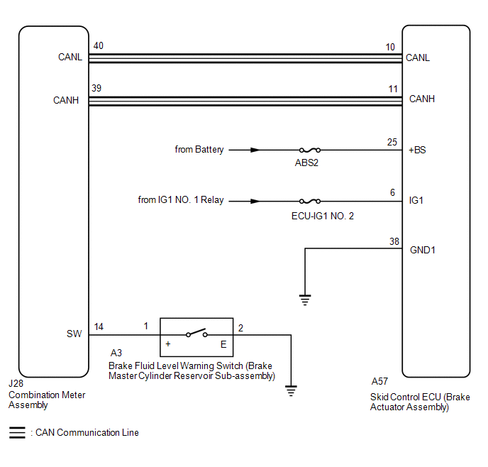 CAUTION / NOTICE / HINT NOTICE:
PROCEDURE
(a) Check if CAN communication system DTCs are output. Click here
(a) Check if the skid control ECU (brake actuator assembly) connector is securely connected. OK: The connector is securely connected.
(a) Check the battery voltage. Standard Voltage:
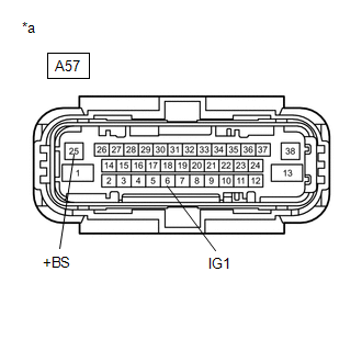
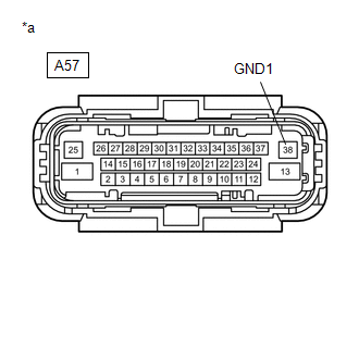
(b) Make sure that there is no looseness at the locking part and the connecting part of the connector. OK: The connector is securely connected. (c) Disconnect the A57 skid control ECU (brake actuator assembly) connector. (d) Check both the connector case and the terminals for deformation and corrosion. OK: No deformation or corrosion. (e) Measure the voltage according to the value(s) in the table below. Standard Voltage:
(b) Measure the resistance according to the value(s) in the table below. Standard Resistance:
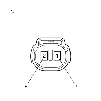
(b) Reconnect the A57 skid control ECU (brake actuator assembly) connector. (c) Remove the reservoir filler cap and strainer. (d) Make sure that there is no looseness at the locking part and the connecting part of the connector. OK: The connector is securely connected. (e) Disconnect the A3 brake fluid level warning switch (brake master cylinder reservoir sub-assembly) connector. (f) Check both the connector case and the terminals for deformation and corrosion. OK: No deformation or corrosion. (g) Measure the resistance according to the value(s) in the table below. HINT: A float is located inside the reservoir. Its position changes according to the brake fluid level. Standard Resistance:
HINT: If there is no problem after finishing the above check, adjust the brake fluid level to the MAX level.
(a) Make sure that there is no looseness at the locking part and the connecting part of the connector. OK: The connector is securely connected. (b) Disconnect the J28 combination meter assembly connector. (c) Check both the connector case and the terminals for deformation and corrosion. OK: No deformation or corrosion. (d) Measure the resistance according to the value(s) in the table below. Standard Resistance:
(a) Reconnect the A3 brake fluid level warning switch (brake master cylinder reservoir sub-assembly) connector. (b) Reconnect the J28 combination meter assembly connector. (c) Enter the following menus: Chassis / ABS/VSC/TRAC / Data List. ABS/VSC/TRAC
(d) Check the Techstream display condition of the brake warning light.
|
Toyota Tundra Service Manual > Vehicle Stability Control System: Acceleration Sensor Internal Circuit (C1419,C1435)
DESCRIPTION These DTCs are stored when the skid control ECU (brake actuator assembly) receives an internal malfunction signal from the yaw rate and acceleration sensor (airbag sensor assembly). DTC No. Detection Item DTC Detection Condition Trouble Area C1419 Acceleration Sensor Internal Circuit Wit ...