Toyota Tundra Service Manual: Open in ABS Motor Relay Circuit (C146C)

DESCRIPTION

The ABS motor relay supplies power to the pump motor. While the ABS is activated, the skid control ECU (brake actuator assembly) turns the ABS motor relay on to operate the pump motor.

If the voltage supplied to the ABS motor relay (+BM) is too low due to low voltage from the battery or alternator, this DTC may be stored.

DTC No.

Detection Item

DTC Detection Condition

Trouble Area

C146C

Open in ABS Motor Relay Circuit

When the ABS motor relay is not actuated, the voltage supplied to the ABS motor relay (+BM) is continuously below approximately 6 V for 1.8 seconds.

  • ABS1 fuse
  • ABS motor relay circuit
  • ABS motor relay (brake actuator assembly)

WIRING DIAGRAM

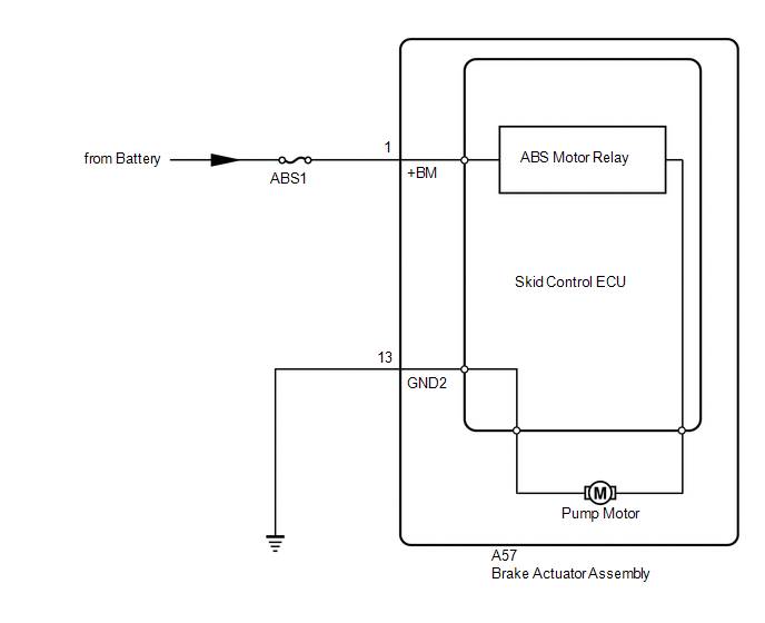
CAUTION / NOTICE / HINT

NOTICE:

  • When replacing the skid control ECU (brake actuator assembly), perform system variant learning and acceleration sensor zero point calibration.

    Click here

  • Inspect the fuses for circuits related to this system before performing the following procedure.

HINT:

When C1241 and/or C1417 is output together with C146C, inspect and repair the trouble areas indicated by C1241 and/or C1417 first.

for C1241: Click here

for C1417: Click here

PROCEDURE

1.

PERFORM ACTIVE TEST USING TECHSTREAM (ABS MOTOR RELAY)

(a) Connect the Techstream to the DLC3.

(b) Start the engine.

(c) Enter the following menus: Chassis / ABS/VSC/TRAC / Active Test.

ABS/VSC/TRAC

Tester Display

Measurement Item

Control Range

Diagnostic Note

Motor Relay

ABS motor relay

Relay OFF/ON

Operating sound of motor can be heard

(d) Check the operating sound of the pump motor when operating it using the Techstream.

Result

Proceed to

Operating sound is heard

A

Operating sound is not heard

B

B

GO TO STEP 3

A

2.

RECONFIRM DTC

HINT:

This DTC is stored when a problem is identified in the skid control ECU (brake actuator assembly).

The ABS motor relay is in the skid control ECU (brake actuator assembly).

Therefore, ABS motor relay inspection and ABS motor relay unit inspection cannot be performed. Be sure to check if the DTC is output again before replacing the skid control ECU (brake actuator assembly).

(a) Clear the DTCs.

Click here

(b) Turn the ignition switch off.

(c) Start the engine.

(d) Drive the vehicle at a speed of 9 km/h (6 mph) or more for 30 seconds or more.

(e) Check if the same DTC is output.

Click here

Result

Proceed to

C146C is not output

A

C146C is output

B

HINT:

  • If a speed signal of 9 km/h (6 mph) or more is received by the skid control ECU (brake actuator assembly) with the ignition switch ON, the skid control ECU (brake actuator assembly) performs self diagnosis of the motor circuit.
  • If the normal system code is output (no DTCs are output), slightly jiggle the connectors, wire harness, and fuses of the skid control ECU (brake actuator assembly).
  • If any DTCs are output while jiggling a connector or wire harness of the skid control ECU (brake actuator assembly), inspect and repair the connector or wire harness.
  • If no DTCs were output when reconfirming DTCs, checking for intermittent problems is necessary because it is suspected that the original DTCs were stored due to the poor connection of a connector terminal.
A

USE SIMULATION METHOD TO CHECK

B

REPLACE BRAKE ACTUATOR ASSEMBLY

3.

CHECK HARNESS AND CONNECTOR (+BM TERMINAL)

(a) Turn the ignition switch off.

*a

Front view of wire harness connector

(to Skid Control ECU (Brake Actuator Assembly))

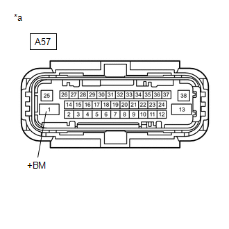
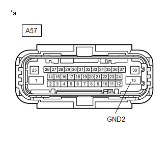
(b) Make sure that there is no looseness at the locking part and the connecting part of the connector.

OK:

The connector is securely connected.

(c) Disconnect the A57 skid control ECU (brake actuator assembly) connector.

(d) Check both the connector case and the terminals for deformation and corrosion.

OK:

No deformation or corrosion.

(e) Measure the voltage according to the value(s) in the table below.

Standard Voltage:

Tester Connection

Condition

Specified Condition

A57-1 (+BM) - Body ground

Always

11 to 14 V

NG

REPAIR OR REPLACE HARNESS OR CONNECTOR (+BM CIRCUIT)

OK

4.

CHECK HARNESS AND CONNECTOR (GND2 TERMINAL)

(a) Measure the resistance according to the value(s) in the table below.

Standard Resistance:

Tester Connection

Condition

Specified Condition

A57-13 (GND2) - Body ground

Always

Below 1 Ω

*a

Front view of wire harness connector

(to Skid Control ECU (Brake Actuator Assembly))

OK

REPLACE BRAKE ACTUATOR ASSEMBLY

NG

REPAIR OR REPLACE HARNESS OR CONNECTOR (GND2 CIRCUIT)

    Brake Warning Light Remains ON

    Open in ABS Solenoid Relay Circuit (C146E)

    See More:

    Toyota Tundra Service Manual > Hood: On-vehicle Inspection
    ON-VEHICLE INSPECTION PROCEDURE 1. INSPECT HOOD SUB-ASSEMBLY (a) Check that the clearance measurements of areas A to D are within the standard range. Standard Clearance: Area Specified Condition A 3.7 to 6.7 mm (0.146 to 0.264 in.) B -1.5 to 1.5 mm (-0.0591 to 0.0591 in.) C (Reference) 25.25 to 28.2 ...

    Toyota Tundra Owners Manual

    Toyota Tundra Service Manual

    © 2024 Copyright www.ttundra.com
    0.0227