DESCRIPTION The skid control ECU monitors the 2WD/4WD state from both the 4 wheel drive control ECU and the A.D.D. detection switch.
WIRING DIAGRAM 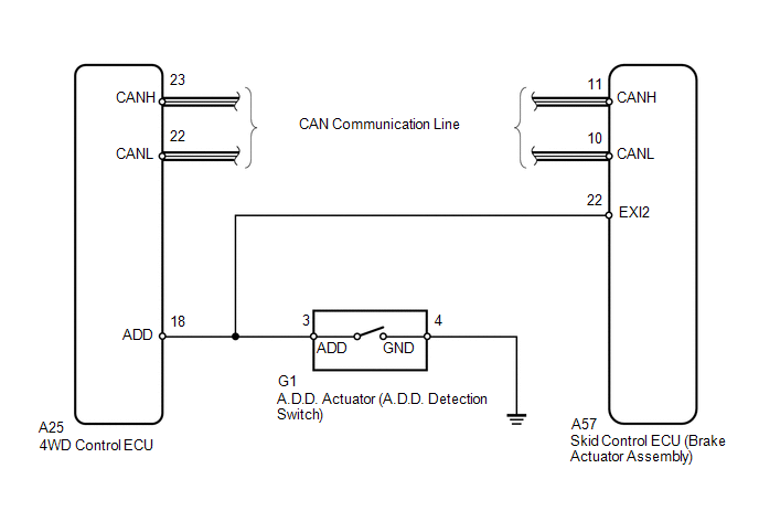 CAUTION / NOTICE / HINT NOTICE: When replacing the VSC actuator assembly, perform zero point calibration. HINT: If the transfer shift actuator cannot change from 2WD to 4WD or 4WD to 2WD, inspect and repair the touch select 2-4 and high-low system first. PROCEDURE
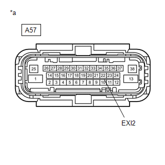
(a) Set the vehicle in 4WD state using the transfer position switch. (b) Turn the ignition switch off. (c) Make sure that there is no looseness at the locking part and the connecting part of the connector. OK: The connector is securely connected.
(e) Check both the connector case and the terminals for deformation and corrosion. OK: No deformation or corrosion. (f) Turn the ignition switch to ON. (g) Measure the voltage according to the value(s) in the table below. Standard Voltage:
(h) Turn the ignition switch off. (i) Connect the A57 skid control ECU (brake actuator assembly) connector. (j) Set the vehicle in 2WD state using the transfer position switch. (k) Disconnect the A57 skid control ECU (brake actuator assembly) connector. (l) Turn the ignition switch to ON. (m) Measure the voltage according to the value(s) in the table below. Standard Voltage:
(a) Make sure that there is no looseness at the locking part and the connecting part of the connector. OK: The connector is securely connected. (b) Disconnect the A25 4WD control ECU connector. (c) Disconnect the G1 A.D.D. actuator connector. (d) Check both the connector case and the terminals for deformation and corrosion. OK: No deformation or corrosion. (e) Measure the resistance according to the value(s) in the table below. Standard Resistance:
(a) Reconnect the A25 4WD control ECU connector. (b) Reconnect the G1 A.D.D. actuator connector. (c) Reconnect the A57 skid control ECU (brake actuator assembly) connector. (d) Measure the resistance according to the value(s) in the table below. 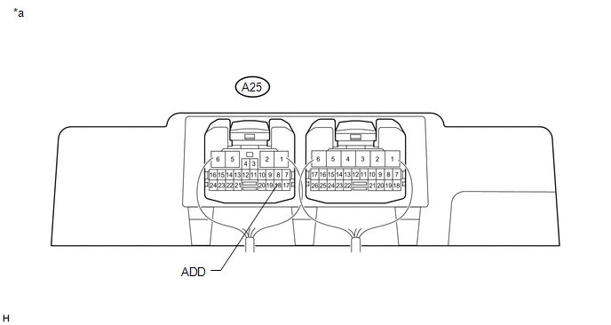
Standard Resistance:
(a) Clear the DTCs. Click here (b) Turn the ignition switch off. (c) Start the engine. (d) Check if the same DTC is output. Click here
|
Toyota Tundra Service Manual > Side Airbag Sensor(for Crewmax): Removal
REMOVAL PROCEDURE 1. PRECAUTION NOTICE: After turning the ignition switch off, waiting time may be required before disconnecting the cable from the battery terminal. Therefore, make sure to read the disconnecting the cable from the battery terminal notice before proceeding with work (See page ). 2. ...