DESCRIPTION When the skid
control ECU (brake actuator assembly) applies the brakes after receiving
a brake request signal from the trailer sway control, the skid control
ECU (brake actuator assembly) operates the stop light switch assembly to
illuminate the stop lights. |
DTC No. | Detection Item |
DTC Detection Condition | Trouble Area | |
C1380 | Stop Light Control Relay Malfunction |
Either condition is met:
- When the voltage at the +BS terminal is between 10 V or more and the
light switch assembly drive output (STPO) is on, a signal is not input
to the STP2 terminal for 2 seconds or more.
- When the voltage at the +BS terminal is between 10 V or more and the
stop light switch assembly drive output (STPO) is off, the signal at the
STP2 terminal is different from the input signal at the STP terminal
for 5 seconds or more.
|
- Wire harness or connector
- Stop light switch assembly
- Skid control ECU (brake actuator assembly)
- ECU-IG1 NO. 2 fuse
- Stop light control relay (VSC ACC)
| WIRING DIAGRAM
Refer to DTC C1249. Click here  CAUTION / NOTICE / HINT
NOTICE:
- When replacing the skid control ECU (brake actuator assembly), perform
system variant learning and acceleration sensor zero point calibration.
Click here
- Inspect the fuses for circuits related to this system before performing the following procedure.
HINT: When DTC C1425 is output together with DTC C1380, inspect and repair the trouble areas indicated by DTC C1425 first.
Click here PROCEDURE
| 1. |
CHECK STOP LIGHT OPERATION | (a) Check that the stop lights come on when the brake pedal is depressed and go off when the brake pedal is released.
OK: |
Condition | Illumination Condition | |
Brake pedal depressed. |
On | | Brake pedal released. |
Off |
| NG |
 | INSPECT STOP LIGHT CIRCUIT |
|
OK |
 | |
| 2. |
CHECK HARNESS AND CONNECTOR (STP2 TERMINAL) |
| (a) Turn the ignition switch off. |
 |
|
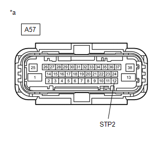
*a | Front view of wire harness connector
(to Skid Control ECU (Brake Actuator Assembly)) | | |
(b) Make sure that there is no looseness at the locking part and the connecting part of the connector.
OK: The connector is securely connected. (c) Disconnect the A57 skid control ECU (brake actuator assembly) connector.
(d) Check both the connector case and the terminals for deformation and corrosion.
OK: No deformation or corrosion. (e) Measure the voltage according to the value(s) in the table below.
Standard Voltage: |
Tester Connection | Condition |
Specified Condition | |
A57-12 (STP2) - Body ground |
Stop light switch assembly on (Brake pedal depressed) |
8 to 14 V | |
A57-12 (STP2) - Body ground |
Stop light switch assembly off (Brake pedal released) |
Below 1.5 V |
| NG |
| REPAIR OR REPLACE HARNESS OR CONNECTOR (STP2 CIRCUIT) |
|
OK | |
| |
| 3. |
CHECK HARNESS AND CONNECTOR (STPO TERMINAL) |
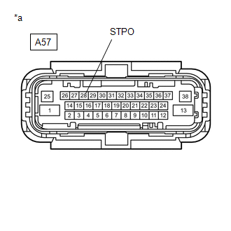
| (a) Measure the voltage according to the value(s) in the table below.
Standard Voltage: |
Tester Connection | Condition |
Specified Condition | |
A57-28 (STPO) - Body ground |
Ignition switch ON |
11 to 14 V | |
 |
|
*a | Front view of wire harness connector
(to Skid Control ECU (Brake Actuator Assembly)) | | |
| NG |
| GO TO STEP 8 |
|
OK | |
| |
| 4. |
PERFORM ACTIVE TEST USING TECHSTREAM (STOP LIGHT RELAY) |
(a) Reconnect the A57 skid control ECU (brake actuator assembly) connector.
(b) Connect the Techstream to the DLC3. (c) Start the engine. (d) Turn the Techstream on.
(e) Enter the following menus: Chassis / ABS/VSC/TRAC / Active Test. ABS/VSC/TRAC |
Tester Display | Measurement Item |
Control Range | Diagnostic Note | |
Stop Light Relay | Stop light Control Relay (VSC ACC) |
Relay OFF/ON | Stop lights come on |
OK: Stop light turns ON/OFF in response to the Techstream operation
| NG |
| GO TO STEP 6 |
|
OK | |
| |
(a) Clear the DTCs.
Click here (b) Enter the following menus: Chassis / ABS/VSC/TRAC / Active Test. ABS/VSC/TRAC |
Tester Display | Measurement Item |
Control Range | Diagnostic Note | |
Stop Light Relay | Stop light control relay (VSC ACC) |
Relay OFF/ON | Stop lights come on |
(c) According to the display on the Techstream, perform the Active Test.
(d) Check if the same DTC is output. Click here
|
Result | Proceed to | |
C1380 is output | A | |
C1380 is not output | B |
| A |
| REPLACE BRAKE ACTUATOR ASSEMBLY |
| B |
| USE SIMULATION METHOD TO CHECK |
| 6. |
INSPECT STOP LIGHT CONTROL RELAY (VSC ACC) |
(a) Turn the ignition switch off. (b) Remove the stop light control relay (VSC ACC) from the engine room relay block and junction block assembly
(c) Inspect the stop light control relay (VSC ACC). Click here
OK: The stop light control relay (VSC ACC) is normal.
| NG |
| REPLACE STOP LIGHT CONTROL RELAY (VSC ACC) |
|
OK | |
| |
| 7. |
CHECK TERMINAL VOLTAGE (STOP LIGHT POWER SOURCE TERMINAL) |
| (a) Measure the voltage according to the value(s) in the table below.
Standard Voltage: |
Tester Connection | Condition |
Specified Condition | |
Stop light control relay (VSC ACC) terminal 5- Body ground |
Always | 11 to 14 V | |
 |
|
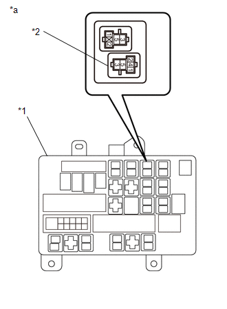
*1 | Engine Room Relay Block and Junction Block Assembly | |
*2 | Stop Light Control Relay (VSC ACC) | |
*a | Component without Stop Light Control Relay (VSC ACC)
(Engine Room Relay Block and Junction Block Assembly) | | |
| OK |
| REPLACE BRAKE ACTUATOR ASSEMBLY |
| NG |
| REPAIR OR REPLACE HARNESS OR CONNECTOR |
| 8. |
INSPECT STOP LIGHT CONTROL RELAY (VSC ACC) |
(a) Turn the ignition switch off. (b) Remove the stop light control relay (VSC ACC) from the engine room relay block and junction block assembly
(c) Inspect the stop light control relay (VSC ACC). Click here
OK: The stop light control relay (VSC ACC) is normal.
| NG |
| REPLACE STOP LIGHT CONTROL RELAY (VSC ACC) |
|
OK | |
| |
| 9. |
CHECK TERMINAL VOLTAGE (STOP LIGHT CONTROL RELAY POWER SOURCE TERMINAL) |
| (a) Measure the voltage according to the value(s) in the table below.
Standard Voltage: |
Tester Connection | Condition |
Specified Condition | |
Stop light control relay (VSC ACC) terminal 1 - Body ground |
Ignition switch ON |
11 to 14 V | | |
|
|
*1 | Engine Room Relay Block and Junction Block Assembly | |
*2 | Stop Light Control Relay (VSC ACC) | |
*a | Component without Stop Light Control Relay (VSC ACC)
(Engine Room Relay Block and Junction Block Assembly) | | |
| NG |
| REPAIR OR REPLACE HARNESS OR CONNECTOR |
|
OK | |
| |
| 10. |
CHECK HARNESS AND CONNECTOR (BRAKE ACTUATOR ASSEMBLY - ENGINE ROOM RELAY BLOCK AND JUNCTION BLOCK ASSEMBLY) |
(a) Turn the ignition switch off. (b) Measure the voltage according to the value(s) in the table below.
Standard Voltage: |
Tester Connection | Condition |
Specified Condition | |
A57-28 (STPO) - Stop light control relay (VSC ACC) terminal 2 |
Always | Below 1 Ω |
| OK |
| REPLACE BRAKE ACTUATOR ASSEMBLY |
| NG |
| REPAIR OR REPLACE HARNESS OR CONNECTOR | | 

