Toyota Tundra Service Manual: High Power Supply Voltage Malfunction (C1417)

DESCRIPTION

If a malfunction is detected in the power supply circuit, the skid control ECU (brake actuator assembly) stores this DTC and the fail-safe function prohibits ABS operation.

This DTC is stored when the +BS terminal voltage deviates due to a malfunction in a power supply or charging system circuit such as the battery or alternator circuit, etc.

DTC No.

Detection Item

DTC Detection Condition

Trouble Area

C1417

High Power Supply Voltage Malfunction

+BS terminal voltage is more than 17.4 V for 0.01 second or more.

  • Battery
  • Charging system
  • Power source circuit
  • Internal power supply circuit of the skid control ECU (brake actuator assembly)

WIRING DIAGRAM

Refer to DTC C1241.

Click here

CAUTION / NOTICE / HINT

NOTICE:

  • When replacing the skid control ECU (brake actuator assembly), perform system variant learning and acceleration sensor zero point calibration.

    Click here

  • Inspect the fuses for circuits related to this system before performing the following procedure.

PROCEDURE

1.

CHECK BATTERY

(a) Check the battery voltage.

Standard Voltage:

Tester Connection

Condition

Specified Condition

Positive (+) terminal - Negative (-) terminal

Ignition switch off

11 to 14 V

NG

CHECK OR REPLACE CHARGING SYSTEM COMPONENT OR BATTERY

OK

2.

CHECK HARNESS AND CONNECTOR (POWER SOURCE TERMINAL)

(a) Make sure that there is no looseness at the locking part and the connecting part of the connector.

OK:

The connector is securely connected.

*a

Front view of wire harness connector

(to Skid Control ECU (Brake Actuator Assembly))

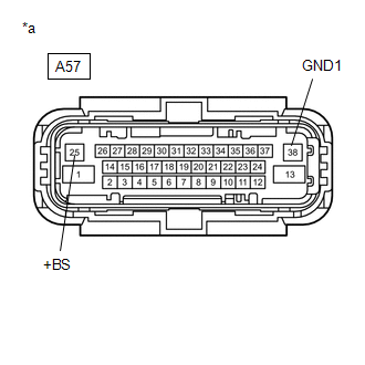
(b) Disconnect the A57 skid control ECU (brake actuator assembly) connector.

(c) Check both the connector case and the terminals for deformation and corrosion.

OK:

No deformation or corrosion.

(d) Measure the voltage according to the value(s) in the table below.

Standard Voltage:

Tester Connection

Condition

Specified Condition

A57-25 (+BS) - Body ground

Always

11 to 14 V

A57-25 (+BS) - A57-38 (GND1)

Always

11 to 14 V

NG

REPAIR OR REPLACE HARNESS OR CONNECTOR (POWER SOURCE CIRCUIT)

OK

3.

RECONFIRM DTC

(a) Turn the ignition switch off.

(b) Reconnect the A57 skid control ECU (brake actuator assembly) connector.

(c) Clear the DTCs.

Click here

(d) Turn the ignition switch off.

(e) Start the engine.

(f) Perform a road test.

(g) Check if the same DTC is output.

Click here

Result

Proceed to

C1417 is not output

A

C1417 is output

B

A

USE SIMULATION METHOD TO CHECK

B

REPLACE BRAKE ACTUATOR ASSEMBLY

    Stop Light Control Relay Malfunction (C1380)

    Acceleration Sensor Internal Circuit (C1419,C1435)

    See More:

    Toyota Tundra Service Manual > Intuitive Parking Assist System: System Description
    SYSTEM DESCRIPTION 1. GENERAL (a) When the vehicle is driven at 10 km/h (6.2 mph) or less, the ultrasonic sensors detect any obstacles at the corners and rear of the vehicle. The system then informs the driver of the distance between the sensors and the obstacles as well as their positions by indica ...

    Toyota Tundra Owners Manual

    Toyota Tundra Service Manual

    © 2024 Copyright www.ttundra.com
    0.0121