DESCRIPTION This DTC is stored when the skid control ECU (brake actuator assembly) receives a +B line open signal from the steering angle sensor (spiral with sensor cable sub-assembly).
WIRING DIAGRAM 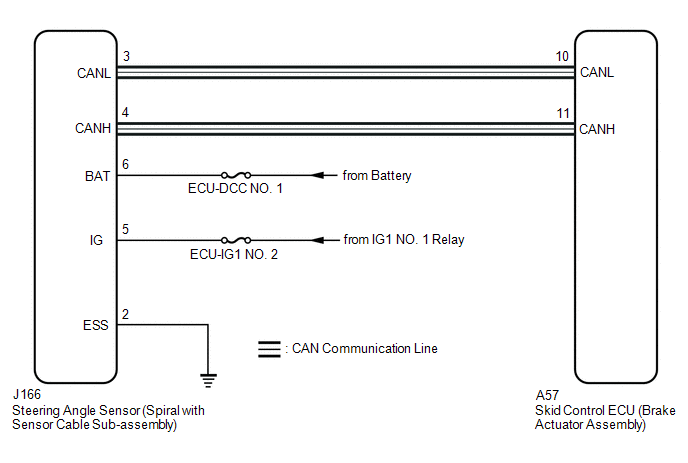 CAUTION / NOTICE / HINT NOTICE: Inspect the fuses for circuits related to this system before performing the following procedure. PROCEDURE
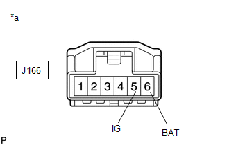
(b) Make sure that there is no looseness at the locking part and the connecting part of the connector. OK: The connector is securely connected. (c) Disconnect the J166 steering angle sensor (spiral with sensor cable sub-assembly) connector. (d) Check both the connector case and the terminals for deformation and corrosion. OK: No deformation or corrosion. (e) Measure the voltage according to the value(s) in the table below. Standard Voltage:
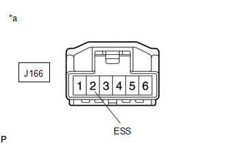
(b) Measure the resistance according to the value(s) in the table below. NOTICE: Before measuring the resistance of the steering angle sensor (spiral with sensor cable sub-assembly), turn the ignition switch off and leave the vehicle for 1 minute or more without operating the key or switches, or opening or closing the doors. Standard Resistance:
|
Toyota Tundra Service Manual > Sfi System: Vehicle Speed Sensor (P0500)
DESCRIPTION The speed sensor detects the wheel speed and sends the appropriate signals to the skid control ECU. The skid control ECU converts these wheel speed signals into a pulse signal and outputs it to the ECM via the combination meter. The ECM determines the vehicle speed based on the frequency ...