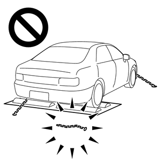
PRECAUTION TROUBLESHOOTING PRECAUTION (a) When there is a malfunction with terminal contact points or part installation problems, removal and installation of the suspected parts may return the system to normal either completely or temporarily. (b) In order to determine the malfunctioning area, be sure to check the conditions at the time the malfunction occurred, such as DTC output and Freeze Frame Data, and record it before disconnecting any connector or removing and installing parts. (c) Since the system may be influenced by malfunctions in systems other than the VSC system, be sure to check for DTCs in other systems. HANDLING PRECAUTION (a) Do not remove or install VSC parts such as the steering angle sensor (spiral with sensor cable sub-assembly) or yaw rate and acceleration sensor (airbag sensor assembly) except when required, as they need to be adjusted correctly after removal and installation. (b) Be sure to perform preparation before work and confirmation after work is completed by following the directions in the repair manual when working on the VSC system. (c) Be sure to remove and install the skid control ECU (brake actuator assembly), sensors, etc. with the ignition switch off unless specified otherwise in the inspection procedure. (d) If the skid control ECU (brake actuator assembly) or a sensor has been removed and installed, it is necessary to check the system for problems after the parts have been reassembled. Check for DTCs using the Techstream. Also check that the system functions and signals received by the ECU are normal using Test Mode (Signal Check). DTC PRECAUTION (a) Warnings for some DTCs cannot be cleared only by repairing the malfunctioning parts. If the warning is displayed after repair work, the DTC should be cleared after turning the ignition switch off. NOTICE: If a DTC for a malfunctioning part reappears after it was cleared, then it has been stored again. (b) When 2 or more DTCs are detected, perform diagnosis for each DTC, one by one until the problem is identified. CHASSIS DYNAMOMETER PRECAUTION When testing with a 2-wheel drum tester such as speedometer tester, combination tester for the speedometer and brakes, or chassis dynamometer, or when jacking up the front wheels and turning the wheels, perform the following procedure to enter Inspection Mode and disable the TRAC and VSC systems. HINT: For 4WD vehicles, make sure that the transfer mode is 2WD. CAUTION:
NOTICE: Secure the vehicle with lock chains for safety. HINT:
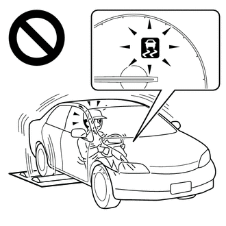
(a) Activating Inspection Mode (When Using the Techstream) (1) Ensure that the ignition switch is off and the engine is stopped. (2) Make sure that the shift lever is in P. (3) Connect the Techstream to the DLC3. (4) Start the engine. (5) Turn the Techstream on. (6) Enter the following menus: Chassis / ABS/VSC/TRAC / Utility / Inspection Mode. (7) Check that the TRAC OFF and VSC OFF indicator lights come on. HINT:
(b) Activating Inspection Mode (When not Using the Techstream) HINT: Perform steps "C" to "H" within 30 seconds. (1) Ensure that the ignition switch is off and the engine is stopped (Step "A"). (2) Make sure that the shift lever is in P (Step "B"). (3) Start the engine (Step "C"). (4) Apply the parking brake (Step "D"). (5) Release and depress the brake pedal twice: release→depress→release→depress (Step "E"). (6) While holding the brake pedal down, release and apply the parking brake twice: release→apply→release→apply (Step "F"). (7) With the parking brake applied, depress and release the brake pedal twice: release→depress→release→depress (Step "G"). (8) Release the brake pedal. (9) Check that the TRAC OFF and VSC OFF indicator lights come on (Step "H"). HINT:
CAN COMMUNICATION SYSTEM PRECAUTION (a) The CAN communication system is used for communication between the skid control ECU (brake actuator assembly), steering angle sensor (spiral with sensor cable sub-assembly), yaw rate and acceleration sensor (airbag sensor assembly) and other ECUs. If there is a malfunction in a CAN communication line, communication DTCs related to the affected systems will be stored. (b) If any CAN communication DTCs are output, repair the malfunction, then troubleshoot the VSC system while communication is normal. (c) In order to enable CAN communication, a specific type of wiring is used for the CAN communication lines. The wiring used for each communication line is a twisted pair of wires that have an equal length. A bypass wire should not be used because the data being transmitted will be corrupted. |
Toyota Tundra Service Manual > Rear Door Lock(for Crewmax): Installation
INSTALLATION PROCEDURE 1. INSTALL REAR DOOR INSIDE LOCKING CABLE ASSEMBLY LH 2. INSTALL REAR DOOR LOCK REMOTE CONTROL CABLE ASSEMBLY LH 3. INSTALL REAR DOOR LOCK ASSEMBLY LH 4. INSTALL REAR DOOR GLASS SUB-ASSEMBLY LH 5. INSTALL REAR DOOR REAR LOWER WINDOW FRAME SUB-ASSEMBLY LH 6. INSTALL REAR DOOR G ...