Toyota Tundra Service Manual: Components

COMPONENTS

ILLUSTRATION
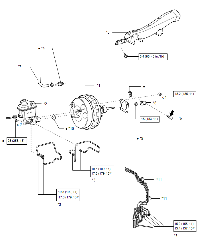
*1

BRAKE BOOSTER ASSEMBLY

*2

BRAKE MASTER CYLINDER SUB-ASSEMBLY

*3

BRAKE TUBE

*4

BRAKE VACUUM CHECK VALVE ASSEMBLY

*5

NO. 3 AIR DUCT SUB-ASSEMBLY

*6

PUSH ROD PIN

*7

VACUUM HOSE ASSEMBLY

*8

CLEVIS

*9

BRAKE BOOSTER GASKET

*10

BRAKE MASTER CYLINDER SEAL

*11

NO. 2 BRAKE TUBE CLAMP

-

-

N*m (kgf*cm, ft.*lbf): Specified torque

*

For use with a union nut wrench

Non-reusable part

Lithium soap base glycol grease

    Brake Booster

    Installation

    See More:

    Toyota Tundra Service Manual > Lighting System: Parking Brake Switch Circuit
    DESCRIPTION The main body ECU (multiplex network body ECU) detects the condition of the parking brake switch assembly. WIRING DIAGRAM PROCEDURE 1. READ VALUE USING TECHSTREAM (a) Using the Techstream, read the Data List. Click here Main Body Tester Display Measurement Item / Range Normal Condition D ...

    Toyota Tundra Owners Manual

    Toyota Tundra Service Manual

    © 2025 Copyright www.ttundra.com
    0.0124