INSTALLATION PROCEDURE 1. INSTALL BRAKE VACUUM CHECK VALVE ASSEMBLY 2. INSTALL BRAKE BOOSTER ASSEMBLY (a) Install the clevis. (b) Install a new brake booster gasket to the brake booster.
3. INSTALL PUSH ROD PIN 4. INSTALL NO. 3 AIR DUCT SUB-ASSEMBLY 5. INSTALL LOWER NO. 1INSTRUMENT PANEL AIR BAG ASSEMBLY 6. CONNECT VACUUM HOSE ASSEMBLY (a) Connect the vacuum hose onto the check valve. NOTICE: Do not use lubricant when installing a vacuum hose on the brake booster and check valve sides. 7. INSTALL BRAKE MASTER CYLINDER SUB-ASSEMBLY Click here
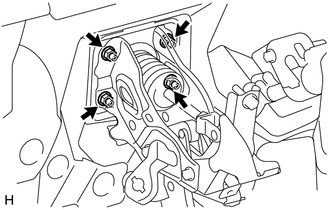
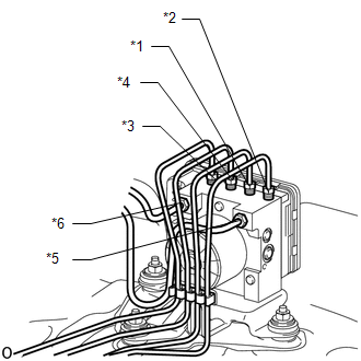
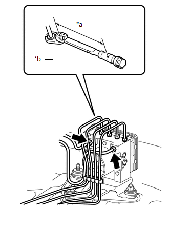
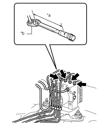
8. CONNECT BRAKE TUBE
(d) Attach the clamp. (e) Attach the 4 claws and connect the 2 No. 2 brake tube clamp. 9. CONNECT CABLE TO NEGATIVE BATTERY TERMINAL NOTICE: When disconnecting the cable some systems need to be initialized after the cable is reconnected (See page
10. CHECK AND ADJUST BRAKE PEDAL (a) Check and adjust brake pedal (See page 11. INSPECT BRAKE BOOSTER 12. BLEED BRAKE SYSTEM |
Toyota Tundra Service Manual > Starter(for 1.6 Kw Type): Installation
INSTALLATION PROCEDURE 1. INSTALL STARTER ASSEMBLY (a) Install the flywheel housing side cover. (b) Install the starter with the 2 bolts. Torque: 37 N·m {377 kgf·cm, 27 ft·lbf} (c) Connect the starter wire with the nut. Torque: 9.8 N·m {100 kgf·cm, 87 in·lbf} (d) Connect the starter connector. ...