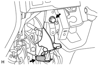
INSTALLATION PROCEDURE 1. INSTALL BRAKE PEDAL PAD (a) Install the brake pedal pad onto the brake pedal. 2. INSTALL BRAKE PEDAL SUPPORT ASSEMBLY (a) Install the brake pedal support assembly with the 4 nuts. Torque: 15.2 N·m {155 kgf·cm, 11 ft·lbf} 3. INSTALL INSTRUMENT PANEL REINFORCEMENT ASSEMBLY Click here 4. CONNECT BRAKE PEDAL SUPPORT ASSEMBLY
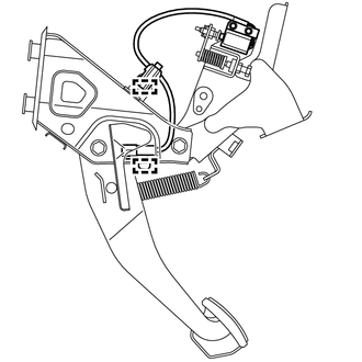
(b) Apply lithium soap base glycol grease to the inner surface of the hole on the brake pedal and return spring mounting bracket of the brake pedal support assembly. (c) Install the brake pedal return spring.
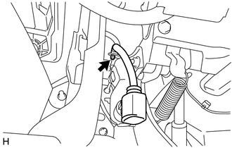
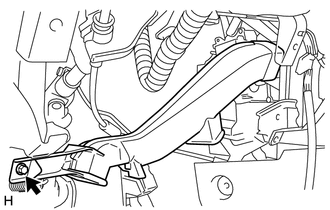
(e) Connect the wire harness clamp to the brake pedal support assembly.
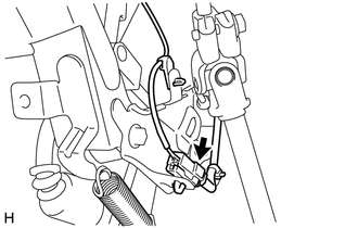
5. INSTALL PUSH ROD PIN (a) Apply a light coat of lithium soap base glycol grease to the inner surface of the hole on the brake pedal lever. (b) Set the push rod clevis in place, insert the push rod pin from outside the vehicle and then install a new clip. NOTICE: After assembly, check that the pedal operates smoothly. 6. INSTALL STOP LIGHT SWITCH MOUNTING ADJUSTER (a) Install the stop light switch mounting adjuster. 7. INSTALL STOP LIGHT SWITCH ASSEMBLY 8. INSTALL NO. 3 AIR DUCT SUB-ASSEMBLY
9. INSTALL LOWER NO. 1 INSTRUMENT PANEL AIR BAG ASSEMBLY
10. CONNECT CABLE TO NEGATIVE BATTERY TERMINAL NOTICE: When disconnecting the cable some systems need to be initialized after the cable is reconnected. Click here 11. CHECK AND ADJUST BRAKE PEDAL (a) Check and adjust brake pedal (See page 12. CHECK MASTER CYLINDER PRESSURE SENSOR SIGNAL (a) Check the master cylinder pressure sensor signal (See page
|
Toyota Tundra Service Manual > Navigation System: Confirm Vehicle Headunit Functionality
PROCEDURE 1. CHECK CUSTOMER'S CELLULAR PHONE COMPATIBILITY (a) Go to TIS "Bluetooth" Compatibility Portal and check if the cellular phone is compatible. Result Result Proceed to Cellular phone is compatible A Cellular phone is not compatible B HINT:It is important to check the cellular phone compati ...