DISASSEMBLY CAUTION / NOTICE / HINT HINT:
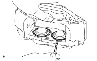
PROCEDURE 1. REMOVE CYLINDER BOOT
2. REMOVE FRONT DISC BRAKE PISTON
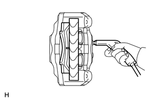
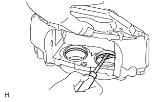
(b) Install a wooden plate between the pistons of the disc brake caliper to prevent the pistons from jumping out. (c) Using an air gun, gradually apply compressed air and remove the 2 disc brake pistons from the cylinder. CAUTION: Do not place your fingers in front of the pistons when using compressed air. (d) Remove the brake pad and wooden plate. (e) Temporarily install the 2 disc brake pistons that were removed. Then install the disc brake pad to the side in which the 2 disc brake pistons were temporarily installed. (f) Install a wooden plate between the pistons of the disc brake caliper to prevent the pistons from jumping out. (g) Using an air gun, gradually apply compressed air and remove the 2 disc brake pistons from the other side of the cylinder. (h) Remove the 2 disc brake pistons which were temporarily installed. 3. REMOVE PISTON SEAL
4. REMOVE FRONT DISC BRAKE BLEEDER PLUG CAP 5. REMOVE FRONT DISC BRAKE BLEEDER PLUG |
Toyota Tundra Service Manual > Radio Receiver(for Floor Shift Type): Installation
INSTALLATION PROCEDURE 1. INSTALL STEREO COMPONENT TUNER ASSEMBLY (w/ Satellite Radio) 2. INSTALL NO. 2 RADIO RECEIVER BRACKET (a) w/o Satellite Radio: Install the No. 2 radio receiver bracket with the 3 bolts. Torque: 3.5 N·m {36 kgf·cm, 31 in·lbf} (b) w/ Satellite Radio: Install the No. 2 radio ...