Toyota Tundra Service Manual: Removal

REMOVAL

CAUTION / NOTICE / HINT

HINT:

  • Use the same procedures for the LH side and RH side.
  • The procedures listed below are for the LH side.

PROCEDURE

1. REMOVE FRONT WHEEL

2. REMOVE FRONT DISC BRAKE PAD KIT

(a) Remove the pin hold clip.

NOTICE:

The pin hold clip can be used again if it has sufficient rebound; no deformation or wear; and has had all rust, dirt and foreign matter cleaned off.

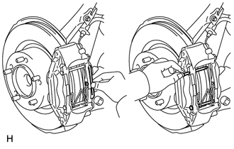
(b) Remove the hole pins.

(c) Remove the front disc brake anti-rattle spring.

NOTICE:

The anti-rattle spring can be used again if it has sufficient rebound; no deformation, cracks or wear; and has had all rust, dirt and foreign matter cleaned off.

(d) Remove the 2 pads from the disc brake caliper.

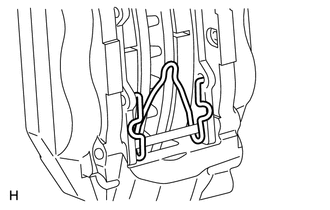
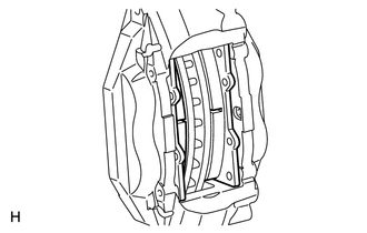
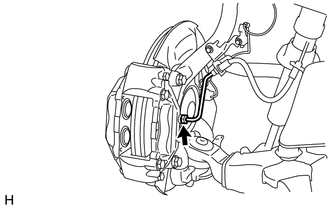
(e) Remove the No. 1 and No. 2 anti-squeal shims from each pad.

3. DRAIN BRAKE FLUID

NOTICE:

Wash brake fluid off immediately if it is spilled on any painted surface.

4. DISCONNECT NO. 7 FRONT BRAKE TUBE

(a) Using a union nut wrench, disconnect the front brake tube from the disc brake caliper.

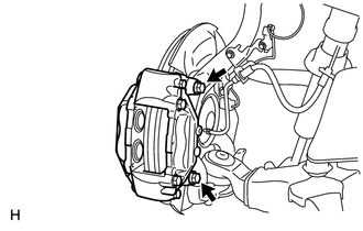
5. REMOVE FRONT DISC BRAKE CALIPER ASSEMBLY LH

(a) Remove the 2 bolts and disc brake caliper from the knuckle.

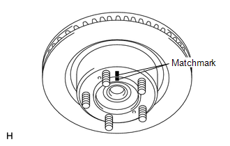
6. REMOVE FRONT DISC

(a) Put matchmarks on the front disc and axle hub if planning to reuse the disc.

(b) Remove the front disc.

    Reassembly

    Rear Brake Flexible Hose

    See More:

    Toyota Tundra Service Manual > Vehicle Stability Control System: Brake Pedal Load Sensing Switch OFF Stuck Malfunction (C1430,C1431)
    DESCRIPTION The brake pedal load sensing switch turns on when the brake pedal is depressed with a force exceeding a predetermined level. The skid control ECU uses this circuit to detect if the brake pedal is depressed or not. DTC No. Detection Item DTC Detection Condition Trouble Area C1430 Brake Pe ...

    Toyota Tundra Owners Manual

    Toyota Tundra Service Manual

    © 2024 Copyright www.ttundra.com
    0.0259