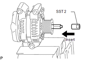
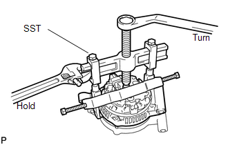
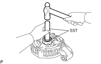
DISASSEMBLY PROCEDURE 1. REMOVE GENERATOR PULLEY 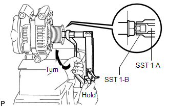 SST: 09820-63011 09820-06010 09820-06021
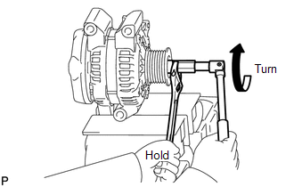
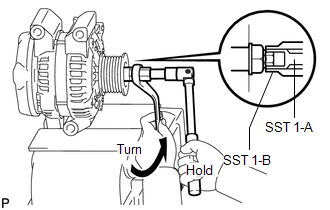
(a) Clamp the generator housing stay in a vise. (b) Install SST 1-A to the pulley shaft. (c) Install SST 1-B to SST 1-A. (d) Hold SST 1-A with a torque wrench, and tighten SST 1-B clockwise to the specified torque. Torque: 39 N·m {398 kgf·cm, 29 ft·lbf} NOTICE: Check that SST is secured on the rotor shaft.
(g) Remove SST 2 from the generator.
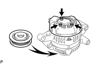
(i) Remove the pulley nut and pulley. 2. REMOVE GENERATOR REAR END COVER
(b) Remove the 3 nuts and end cover.
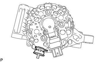
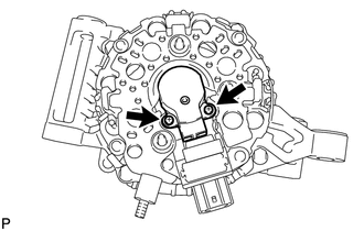
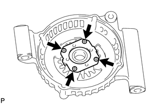
3. REMOVE GENERATOR BRUSH HOLDER ASSEMBLY
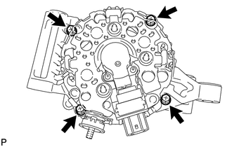
4. REMOVE GENERATOR COIL ASSEMBLY
(c) Remove the generator washer. 5. REMOVE GENERATOR ROTOR ASSEMBLY 6. REMOVE GENERATOR DRIVE END FRAME BEARING
|
Toyota Tundra Service Manual > Power Window Control System(w/o Jam Protection Function): Data List / Active Test
DATA LIST / ACTIVE TEST 1. DATA LIST HINT: Using the Techstream to read the Data List allows the values or states of switches, sensors, actuators and other items to be read without removing any parts. This non-intrusive inspection can be very useful because intermittent conditions or signals may be ...