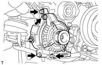
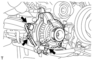
INSTALLATION PROCEDURE 1. INSTALL GENERATOR ASSEMBLY
(c) Connect the generator connector. (d) Connect the generator wire with the nut. Torque: 9.8 N·m {100 kgf·cm, 87 in·lbf} (e) Install the terminal cap. 2. CONNECT VANE PUMP ASSEMBLY 3. CONNECT POWER STEERING OIL PRESSURE SWITCH CONNECTOR
4. INSTALL FRONT FENDER APRON SEAL RH 5. INSTALL AIR CLEANER ASSEMBLY 6. INSTALL FAN AND GENERATOR V BELT (a) Install the fan and generator V belt (See page
7. CONNECT CABLE TO NEGATIVE BATTERY TERMINAL |
Toyota Tundra Service Manual > Cylinder Block: Replacement
REPLACEMENT PROCEDURE 1. REPLACE STRAIGHT PIN NOTICE: It is not necessary to remove the straight pin unless it is being replaced. (a) Remove the straight pins. (b) Using a plastic-faced hammer, tap in new straight pins to the cylinder block. Standard Straight Pin: Item Height Width Protrusion Pin A ...