REASSEMBLY PROCEDURE 1. REMOVE GENERATOR DRIVE END FRAME BEARING
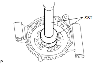
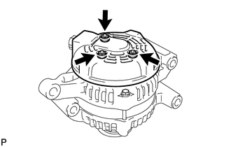
2. INSTALL GENERATOR ROTOR ASSEMBLY
(b) Install the rotor to the drive end frame. 3. INSTALL GENERATOR COIL ASSEMBLY
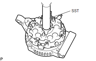
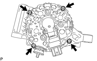
4. INSTALL GENERATOR BRUSH HOLDER ASSEMBLY
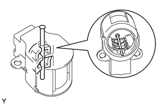
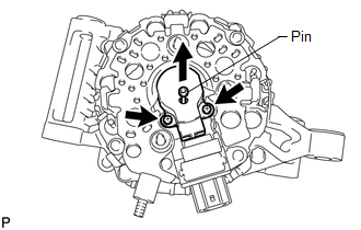
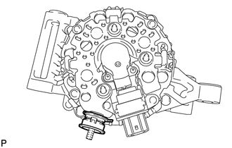
(c) Pull out the pin from the generator brush holder. 5. INSTALL GENERATOR REAR END COVER
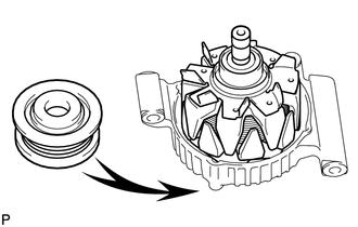
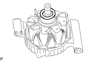
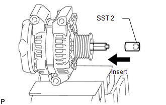
6. INSTALL GENERATOR PULLEY 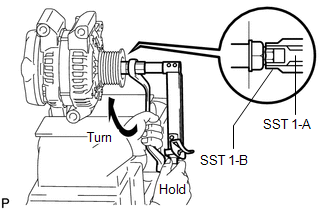
SST: 09820-63011 09820-06010 09820-06021
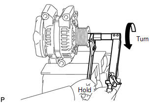
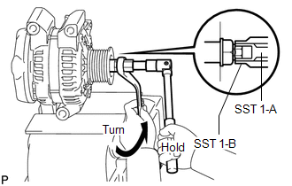
(a) Clamp the generator housing stay in a vise. (b) Install SST 1-A to the pulley shaft. (c) Install SST 1-B to SST 1-A. (d) Install the pulley onto the rotor shaft by tightening the pulley nut by hand. (e) Hold SST 1-A with a torque wrench, and tighten SST 1-B clockwise to the specified torque. Torque: 39 N·m {398 kgf·cm, 29 ft·lbf} NOTICE: Check that SST is secured to the rotor shaft.
(h) Remove SST 2 from the generator.
(j) Turn the pulley and check that the pulley moves smoothly. |
Toyota Tundra Service Manual > Front Door Lock(for Crewmax): Installation
INSTALLATION CAUTION / NOTICE / HINT HINT: Use the same procedures for the LH side and RH side. The procedures listed below are for the LH side. A bolt without a torque specification is shown in the standard bolt chart (See page ). PROCEDURE 1. INSTALL FRONT DOOR INSIDE LOCKING CABLE ASSEMBLY LH 2. ...