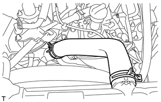
REMOVAL PROCEDURE 1. REMOVE NO. 1 ENGINE UNDER COVER 2. DRAIN ENGINE COOLANT 3. REMOVE V-BANK COVER SUB-ASSEMBLY 4. REMOVE AIR CLEANER ASSEMBLY 5. REMOVE INLET RADIATOR HOSE
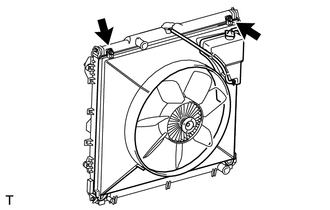
6. REMOVE FAN SHROUD
(b) Remove the fan and generator V-belt (See page
(c) Disconnect the reservoir hose from the upper radiator tank.
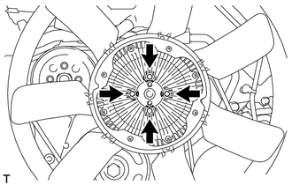
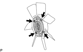
(e) Remove the 4 nuts of the fluid coupling fan, and then remove the shroud together with the fluid coupling fan. NOTICE: Be careful not to damage the radiator core. (f) Remove the fan pulley from the fan bracket. 7. REMOVE FAN
|
Toyota Tundra Service Manual > Can Communication System: Check Bus 4 Lines for Short Circuit
DESCRIPTION There may be a short circuit between the CAN main bus lines and/or CAN branch lines when the resistance between terminals 22 (CA2H) and 7 (CA2L) of the central gateway ECU (network gateway ECU) is below 54 Ω. Symptom Trouble Area *1: for 4WD *2: w/ Trailer Brake Control System Resistanc ...