Toyota Tundra Service Manual: Air Injection Driver

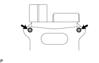
Components

COMPONENTS

ILLUSTRATION
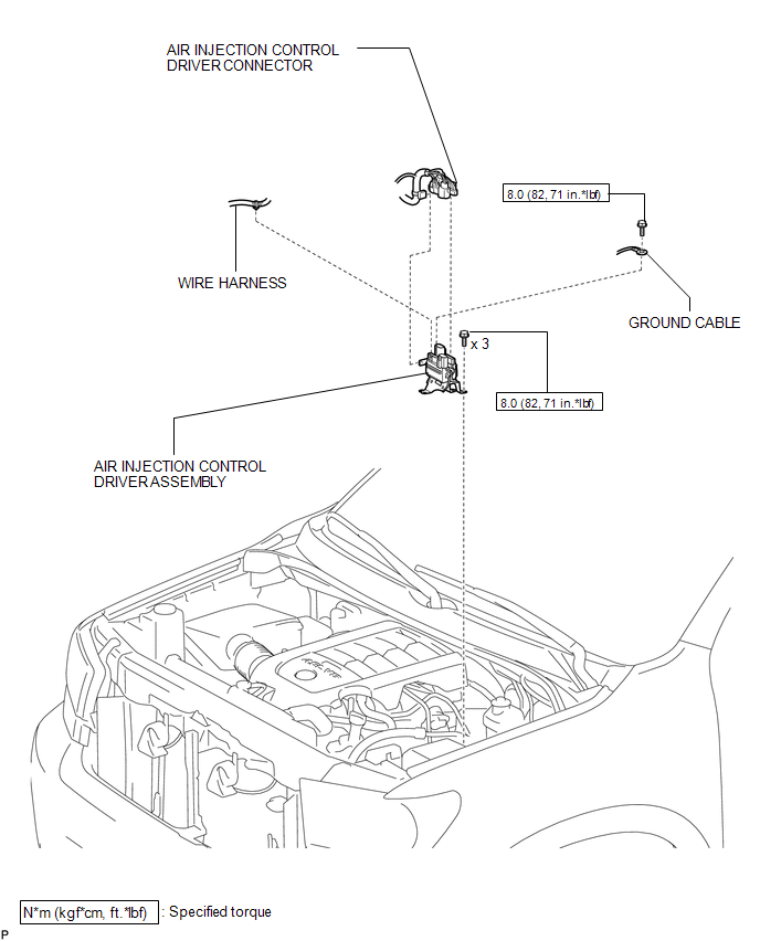
ILLUSTRATION

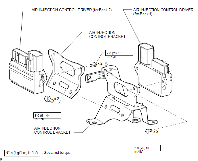
Disassembly

DISASSEMBLY

PROCEDURE

1. REMOVE AIR INJECTION CONTROL DRIVER (for Bank 1)

(a) Remove the 2 bolts.

(b) Remove the 2 screws and air injection control driver.

2. REMOVE AIR INJECTION CONTROL DRIVER (for Bank 2)

(a) Remove the 2 screws and air injection control driver.

Installation

INSTALLATION

PROCEDURE

1. INSTALL AIR INJECTION CONTROL DRIVER ASSEMBLY

(a) Install the air injection control driver with the 3 bolts.

Torque:

8.0 N·m {82 kgf·cm, 71 in·lbf}

(b) Connect the 2 wire harness clamps.

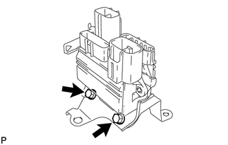
(c) Install the ground cable with the bolt.

Torque:

8.0 N·m {82 kgf·cm, 71 in·lbf}

(d) Connect the 4 air injection control driver connectors.

Reassembly

REASSEMBLY

PROCEDURE

1. INSTALL AIR INJECTION CONTROL DRIVER (for Bank 2)

(a) Install the air injection control driver with the 2 screws.

Torque:

2.0 N·m {20 kgf·cm, 18 in·lbf}

2. INSTALL AIR INJECTION CONTROL DRIVER (for Bank 1)

(a) Install the air injection control driver with the 2 screws.

Torque:

2.0 N·m {20 kgf·cm, 18 in·lbf}

(b) Install the 2 bolts.

Torque:

5.0 N·m {51 kgf·cm, 44 in·lbf}

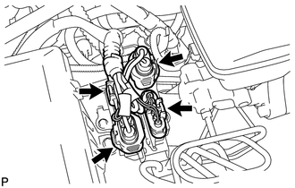
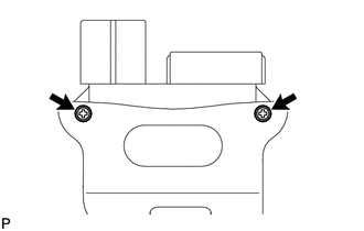
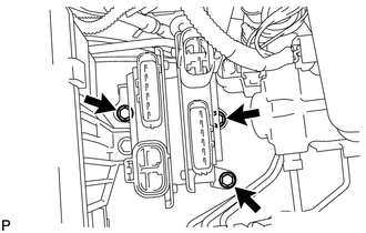
Removal

REMOVAL

PROCEDURE

1. REMOVE AIR INJECTION CONTROL DRIVER ASSEMBLY

(a) Disconnect the 4 air injection control driver connectors.

(b) Remove the bolt and disconnect the ground cable.

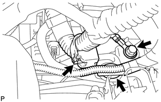
(c) Disconnect the 2 wire harness clamps.

(d) Remove the 3 bolts and air injection control driver.

    1ur-fe Emission Control

    Air Pump

    See More:

    Toyota Tundra Service Manual > Pre-collision System: Fail-safe Chart
    FAIL-SAFE CHART FAIL-SAFE FUNCTION (a) When a malfunction occurs in the pre-collision system, a message will be displayed on the multi-information display and the pre-collision system will be disabled depending on the malfunction. Warning Message Cause DTC No. Conditions to Return to Normal "Pr ...

    Toyota Tundra Owners Manual

    Toyota Tundra Service Manual

    © 2024 Copyright www.ttundra.com
    0.0372