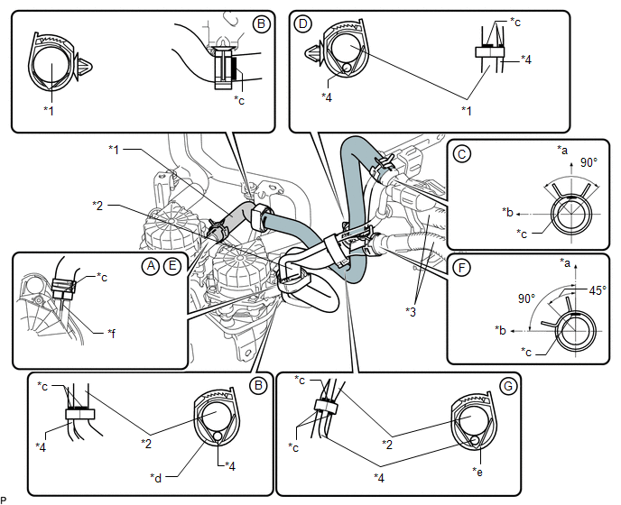
INSTALLATION PROCEDURE 1. INSTALL AIR PUMP ASSEMBLY (a) Connect the 6 air pump insulators to the 2 air pump assemblies and install the 2 air pump assemblies to the air pump bracket. (b) Attach the 2 wire harness clamps to the air pump bracket. 2. INSTALL NO. 1 AIR INJECTION SYSTEM HOSE
3. INSTALL AIR PUMP INLET
(b) Install the 2 bolts. Torque: 8.0 N·m {82 kgf·cm, 71 in·lbf} 4. INSTALL AIR PUMP ASSEMBLY WITH BRACKET
5. INSTALL NO. 3 AIR INJECTION SYSTEM HOSE  Text in Illustration Text in Illustration
(a) Connect the No. 3 air injection system hose, and slide the clamp to secure the hose so that its paint mark aligns with the air pump's rib as shown in the illustration labeled A. (b) Attach the clamp to the No. 3 air injection system hose shown in the illustration labeled B. HINT: Align the paint mark of the No. 3 air injection system hose with the edge of the clamp. (c) Connect the No. 3 air injection system hose to the air tube, and slide the clamp to secure the hose shown in the illustration labeled C. HINT:
(d) Attach the clamp to the No. 3 air injection system hose and wire harness shown in the illustration labeled D. HINT: Align the paint mark of the No. 3 air injection system hose and paint mark of the wire harness with the edge of the clamp. 6. INSTALL NO. 2 AIR INJECTION SYSTEM HOSE (a) Connect the No. 2 air injection system hose, and slide the clamp to secure the hose so that its paint mark aligns with the air pump's rib as shown in the illustration labeled E. (b) Connect the No. 2 air injection system hose to the air tube, and slide the clamp to secure the hose shown in the illustration labeled F. HINT:
(c) Attach the white colored clamp to the No. 2 air injection system hose and wire harness shown in the illustration labeled G. HINT:
(d) Attach the black colored clamp to the No. 2 air injection system hose and wire harness shown in the illustration labeled H. 7. CONNECT FRONT FENDER APRON SEAL RH (a) Connect the front fender apron seal RH to the body panel with the 2 clips. 8. CONNECT FRONT FENDER LINER RH (See page
|
Toyota Tundra Service Manual > Power Tilt And Power Telescopic Steering Column System: Problem Symptoms Table
PROBLEM SYMPTOMS TABLE HINT: Use the table below to help determine the cause of problem symptoms. If multiple suspected areas are listed, the potential causes of the symptoms are listed in order of probability in the "Suspected Area" column of the table. Check each system by checking the suspected a ...