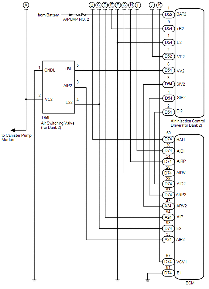
SYSTEM DIAGRAM 1. SECONDARY AIR INJECTION CONTROL SYSTEM DIAGRAM 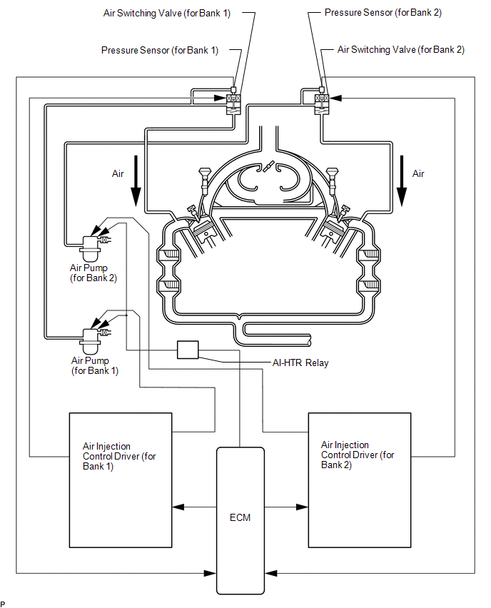 2. SECONDARY AIR INJECTION SYSTEM WIRING DIAGRAM 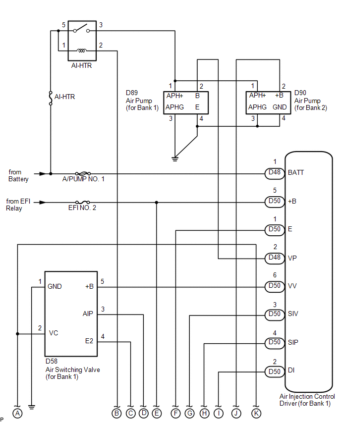
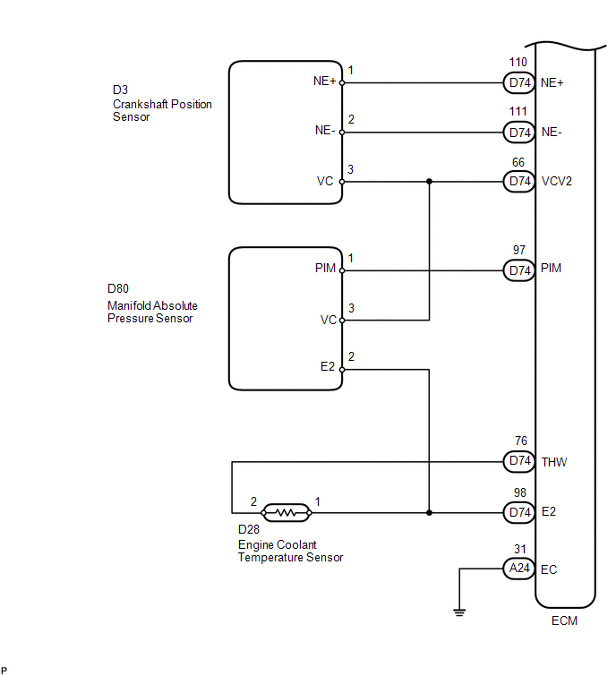
 3. EGR CONTROL SYSTEM DIAGRAM 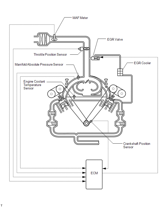 4. EGR CONTROL SYSTEM WIRING DIAGRAM 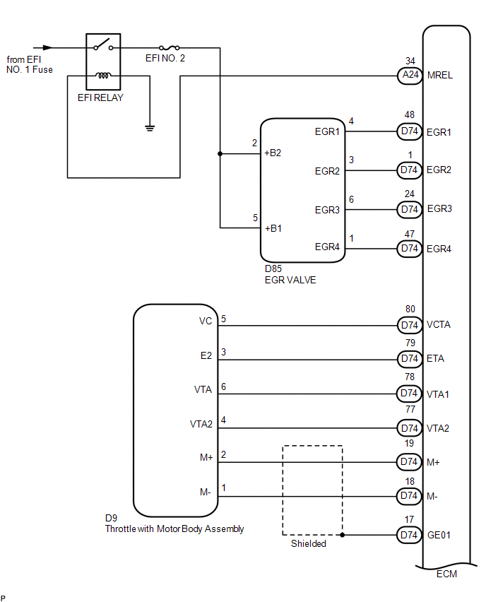
 5. EVAP CONTROL SYSTEM DIAGRAM 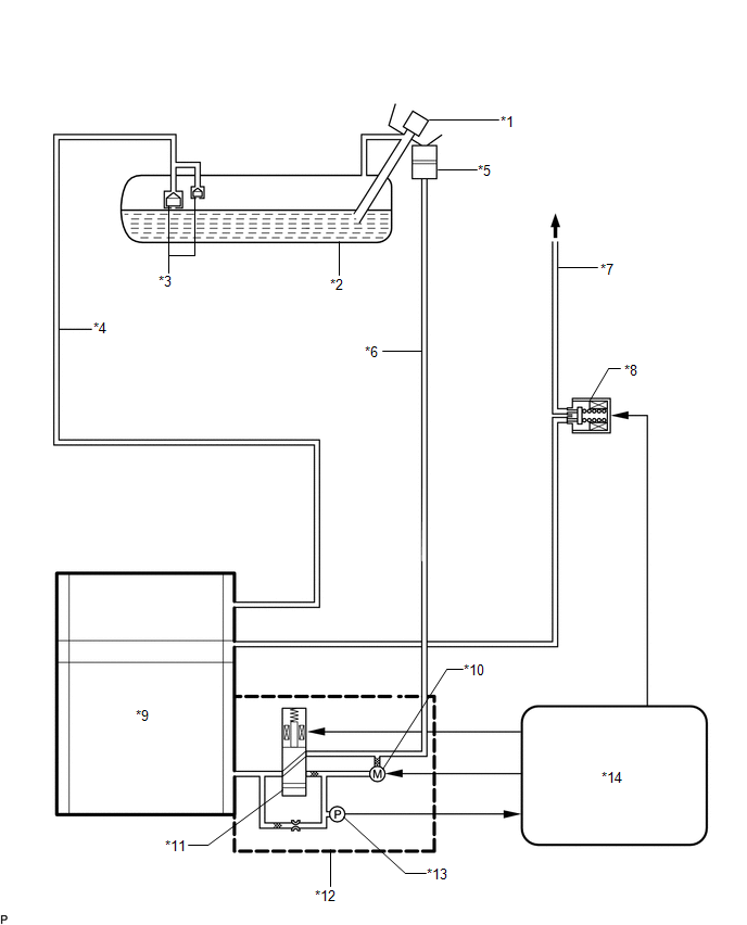 Text in Illustration Text in Illustration
6. EVAP CONTROL SYSTEM WIRING DIAGRAM 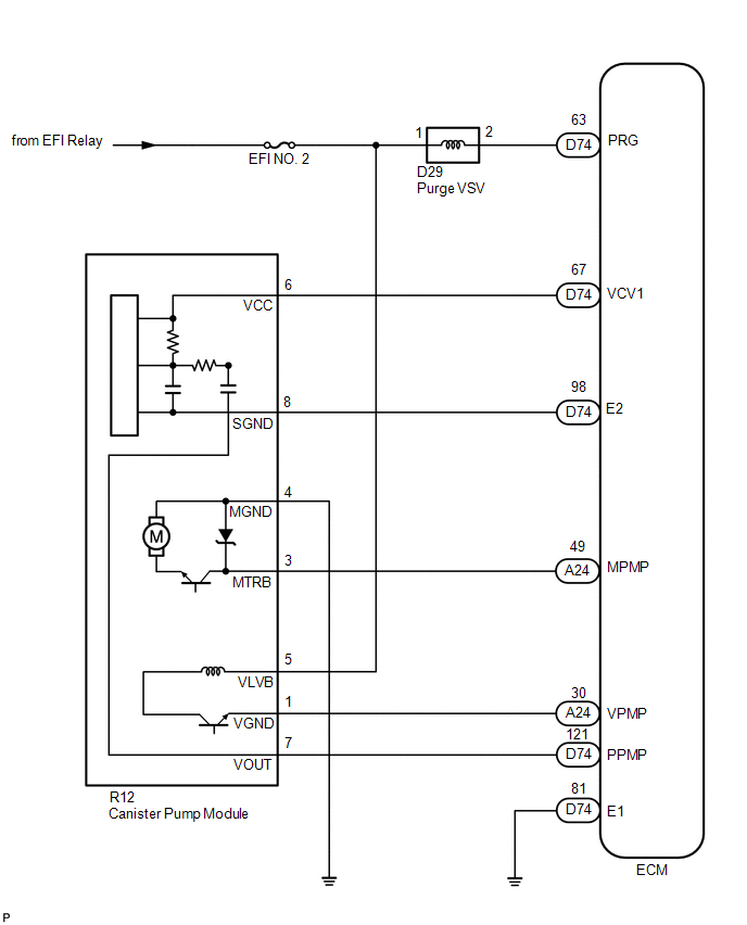 |
Toyota Tundra Service Manual > Camshaft Oil Control Valve: Installation
INSTALLATION PROCEDURE 1. INSTALL CAMSHAFT TIMING OIL CONTROL VALVE ASSEMBLY (for Exhaust Side of Bank 1) (a) Apply a light coat of engine oil to the O-ring. (b) Install a new O-ring to the oil control valve. (c) Install the oil control valve with the bolt. Torque: 10 N·m {102 kgf·cm, 7 ft·lbf} ( ...


