INSTALLATION PROCEDURE 1. INSTALL CAMSHAFT TIMING OIL CONTROL VALVE ASSEMBLY (for Exhaust Side of Bank 1) 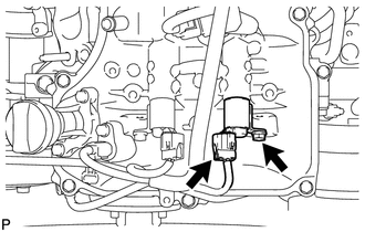 (a) Apply a light coat of engine oil to the O-ring. (b) Install a new O-ring to the oil control valve. (c) Install the oil control valve with the bolt. Torque: 10 N·m {102 kgf·cm, 7 ft·lbf} (d) Connect the oil control valve connector. 2. INSTALL CAMSHAFT TIMING OIL CONTROL VALVE ASSEMBLY (for Intake Side of Bank 1) 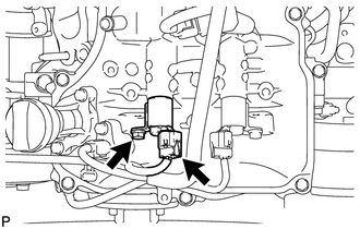 (a) Apply a light coat of engine oil to the O-ring. (b) Install a new O-ring to the oil control valve. (c) Install the oil control valve with the bolt. Torque: 10 N·m {102 kgf·cm, 7 ft·lbf} (d) Connect the oil control valve connector. 3. INSTALL CAMSHAFT TIMING OIL CONTROL VALVE ASSEMBLY (for Intake Side of Bank 2) 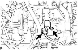 (a) Apply a light coat of engine oil to the O-ring. (b) Install a new O-ring to the oil control valve. (c) Install the oil control valve with the bolt. Torque: 10 N·m {102 kgf·cm, 7 ft·lbf} (d) Connect the oil control valve connector. 4. INSTALL CAMSHAFT TIMING OIL CONTROL VALVE ASSEMBLY (for Exhaust Side of Bank 2) 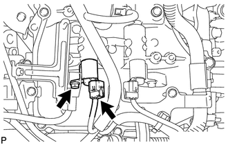 (a) Apply a light coat of engine oil to the O-ring. (b) Install a new O-ring to the oil control valve. (c) Install the oil control valve with the bolt. Torque: 10 N·m {102 kgf·cm, 7 ft·lbf} (d) Connect the oil control valve connector. 5. INSTALL AIR CLEANER HOSE ASSEMBLY 6. INSTALL V-BANK COVER SUB-ASSEMBLY |
Toyota Tundra Service Manual > Horn: High Pitched Horn
Components COMPONENTS ILLUSTRATION *A Type A *B Type B *C Type C - - *1 HIGH PITCHED HORN ASSEMBLY *2 RADIATOR GRILLE SUB-ASSEMBLY N*m (kgf*cm, ft.*lbf): Specified torque - - Inspection INSPECTION PROCEDURE 1. INSPECT HIGH PITCHED HORN ASSEMBLY (a) Apply battery voltage and check operation of the hi ...


