REMOVAL PROCEDURE 1. REMOVE V-BANK COVER SUB-ASSEMBLY 2. REMOVE AIR CLEANER HOSE ASSEMBLY 3. REMOVE CAMSHAFT TIMING OIL CONTROL VALVE ASSEMBLY (for Exhaust Side of Bank 1) 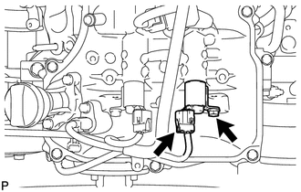 (a) Disconnect the oil control valve connector. (b) Remove the bolt and oil control valve. (c) Remove the O-ring from the oil control valve. 4. REMOVE CAMSHAFT TIMING OIL CONTROL VALVE ASSEMBLY (for Intake Side of Bank 1) 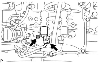 (a) Disconnect the oil control valve connector. (b) Remove the bolt and oil control valve. (c) Remove the O-ring from the oil control valve. 5. REMOVE CAMSHAFT TIMING OIL CONTROL VALVE ASSEMBLY (for Intake Side of Bank 2) 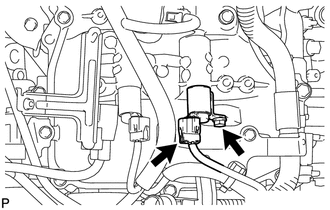 (a) Disconnect the oil control valve connector. (b) Remove the bolt and oil control valve. (c) Remove the O-ring from the oil control valve. 6. REMOVE CAMSHAFT TIMING OIL CONTROL VALVE ASSEMBLY (for Exhaust Side of Bank 2) 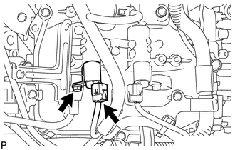 (a) Disconnect the oil control valve connector. (b) Remove the bolt and oil control valve. (c) Remove the O-ring from the oil control valve. |
Toyota Tundra Service Manual > Power Window Master Switch: Removal
REMOVAL PROCEDURE 1. REMOVE FRONT UPPER ARMREST BASE PANEL LH (a) Using a moulding remover A, detach the 2 clips and 5 claws, and remove the front upper armrest base panel LH. (b) Disconnect the master switch connector. 2. REMOVE POWER WINDOW REGULATOR MASTER SWITCH ASSEMBLY (a) Remove the 3 screws ...


