Components COMPONENTS ILLUSTRATION 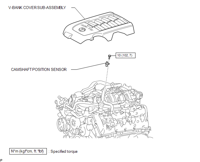 Installation INSTALLATION PROCEDURE 1. INSTALL CAMSHAFT POSITION SENSOR  (a) Install the sensor with the bolt. Torque: 10 N·m {102 kgf·cm, 7 ft·lbf} (b) Connect the sensor connector. 2. INSTALL V-BANK COVER SUB-ASSEMBLY Removal REMOVAL PROCEDURE 1. REMOVE V-BANK COVER SUB-ASSEMBLY 2. REMOVE CAMSHAFT POSITION SENSOR 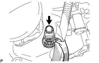 (a) Disconnect the sensor connector. (b) Remove the bolt and sensor. |
Toyota Tundra Service Manual > Tire Pressure Warning System: Tire Pressure Monitor Receiver Communication Stop (B1247)
DESCRIPTION The main body ECU (multiplex network body ECU) and tire pressure warning ECU and receiver are connected using 2 direct lines that they use to communicate with each other. DTC No. Detection Item DTC Detection Condition Trouble Area Note B1247 Tire Pressure Monitor Receiver Communication S ...


