Toyota Tundra Service Manual: Installation

INSTALLATION

CAUTION / NOTICE / HINT

HINT:

Perform "Inspection After Repairs" after replacing the heated oxygen sensor (See page ).

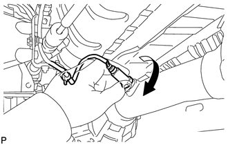
PROCEDURE

1. INSTALL HEATED OXYGEN SENSOR (for Bank 2 Sensor 2)

HINT:

Perform "Inspection After Repairs" after replacing the heated oxygen sensor (See page ).

(a) Install the heated oxygen sensor to the front exhaust pipe assembly by hand.

(b) Using SST, tighten the heated oxygen sensor.

SST: 09224-00010

Torque:

without SST :

44 N·m {449 kgf·cm, 32 ft·lbf}

with SST :

40 N·m {408 kgf·cm, 30 ft·lbf}

Text in Illustration

*a

Fulcrum length

HINT:

  • Use a torque wrench with a fulcrum length of 30 cm (11.8 in.). When using a torque wrench with a fulcrum length that is not 30 cm (11.8 in.), calculate the torque specification for the torque wrench and SST based on the "without SST" torque specification (See page ).
  • Make sure SST and the wrench are connected in a straight line.

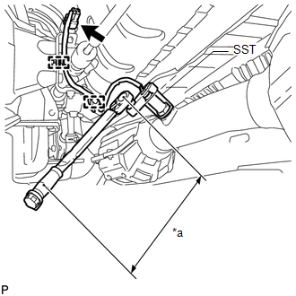
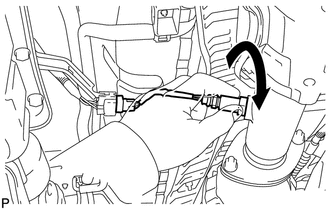
(c) Attach the 2 clamps and connect the the heated oxygen sensor connector.

2. INSTALL HEATED OXYGEN SENSOR (for Bank 1 Sensor 2)

HINT:

Perform "Inspection After Repairs" after replacing the heated oxygen sensor (See page ).

(a) Install the heated oxygen sensor to the front No. 2 exhaust pipe assembly by hand.

(b) Using SST, tighten the heated oxygen sensor.

Text in Illustration

*a

Fulcrum length

SST: 09224-00010

Torque:

without SST :

44 N·m {449 kgf·cm, 32 ft·lbf}

with SST :

40 N·m {408 kgf·cm, 30 ft·lbf}

HINT:

  • Use a torque wrench with a fulcrum length of 30 cm (11.8 in.). When using a torque wrench with a fulcrum length that is not 30 cm (11.8 in.), calculate the torque specification for the torque wrench and SST based on the "without SST" torque specification (See page ).
  • Make sure SST and the wrench are connected in a straight line.

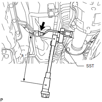
(c) Connect the heated oxygen sensor connector.

3. INSTALL PROPELLER SHAFT HEAT INSULATOR

4. INSPECT FOR EXHAUST GAS LEAK

    Components

    On-vehicle Inspection

    See More:

    Toyota Tundra Service Manual > Lighting System: DRL Relay Circuit
    DESCRIPTION The main body ECU (multiplex network body ECU) controls the daytime running lights. WIRING DIAGRAM CAUTION / NOTICE / HINT NOTICE: Inspect the fuses for circuits related to this system before performing the following procedure. PROCEDURE 1. PERFORM ACTIVE TEST USING TECHSTREAM (a) Using ...

    Toyota Tundra Owners Manual

    Toyota Tundra Service Manual

    © 2024 Copyright www.ttundra.com
    0.0337