Toyota Tundra Service Manual: Knock Sensor

Components

COMPONENTS

ILLUSTRATION

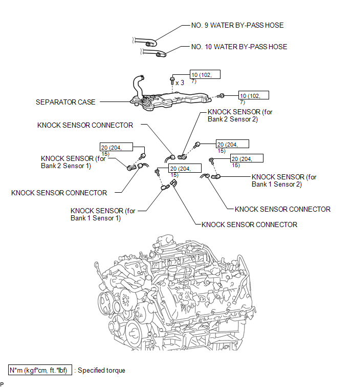
Inspection

INSPECTION

PROCEDURE

1. INSPECT KNOCK SENSOR

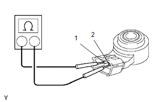
(a) Measure the resistance according to the value(s) in the table below.

Standard Resistance:

Tester Connection

Condition

Specified Condition

1 - 2

20°C (68°F)

120 k to 280 kΩ

If the result is not as specified, replace the knock sensor.

Installation

INSTALLATION

CAUTION / NOTICE / HINT

HINT:

Perform "Inspection After Repairs" after replacing the knock sensor (See page ).

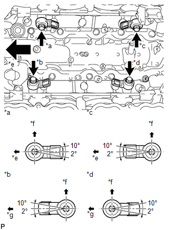
PROCEDURE

1. INSTALL KNOCK SENSOR

HINT:

Perform "Inspection After Repairs" after replacing the knock sensor (See page ).

(a) Install the 4 knock sensors with the 4 bolts so that the sensors are angled as shown in the illustration.

Torque:

20 N·m {204 kgf·cm, 15 ft·lbf}

Text in Illustration

*a

Bank 2 Sensor 1

*b

Bank 1 Sensor 1

*c

Bank 2 Sensor 2

*d

Bank 1 Sensor 2

*e

Front

*f

Upper

*g

Rear

NOTICE:

The acceptable installation angle of the knock sensor is between 10° upward and 2° downward from the horizontal position.

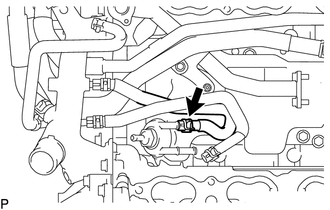
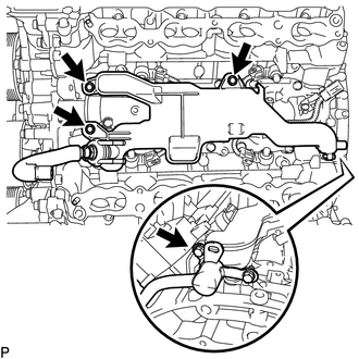
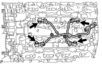
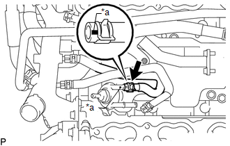
(b) Connect the 4 knock sensor connectors.

2. INSTALL SEPARATOR CASE

(a) Install the separator case with the 4 bolts.

Torque:

10 N·m {102 kgf·cm, 7 ft·lbf}

3. CONNECT NO. 9 WATER BY-PASS HOSE

(a) Connect the No. 9 water by-pass hose to the separator case, and slide the clamp to secure the hose.

Text in Illustration

*a

Blue Mark

HINT:

Make sure the hose color matches the connection area color.

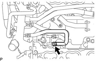
4. CONNECT NO. 10 WATER BY-PASS HOSE

(a) Connect the No. 10 water by-pass hose to the separator case, and slide the clamp to secure the hose.

Text in Illustration

*a

Green Mark

HINT:

Make sure the hose color matches the connection area color.

5. INSTALL INTAKE MANIFOLD

(See page )

Removal

REMOVAL

PROCEDURE

1. REMOVE INTAKE MANIFOLD

(See page )

2. DISCONNECT NO. 10 WATER BY-PASS HOSE

(a) Slide the clamp and remove the No. 10 water by-pass hose from the separator case.

3. DISCONNECT NO. 9 WATER BY-PASS HOSE

(a) Slide the clamp and remove the No. 9 water by-pass hose from the separator case.

4. REMOVE SEPARATOR CASE

(a) Remove the 4 bolts and separator case.

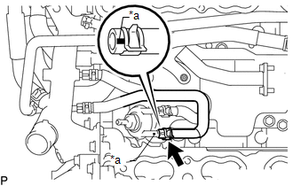
5. REMOVE KNOCK SENSOR

(a) Disconnect the 4 knock sensor connectors.

(b) Remove the 4 bolts and 4 knock sensors.

    Ignition Relay No. 2

    Manifold Absolute Pressure Sensor

    See More:

    Toyota Tundra Service Manual > Air Conditioning System(for Automatic Air Conditioning System): Air Outlet Damper Control Servo Motor Circuit (B1443/43)
    DESCRIPTION The No. 1 damper servo sub-assembly (air outlet servo motor) sends pulse signals to inform the air conditioning amplifier of the damper position. The air conditioning amplifier activates the motor (normal, reverse) based on the signals to move the air outlet damper to any position, which ...

    Toyota Tundra Owners Manual

    Toyota Tundra Service Manual

    © 2023 Copyright www.ttundra.com
    0.0096