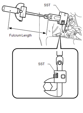
Components COMPONENTS ILLUSTRATION 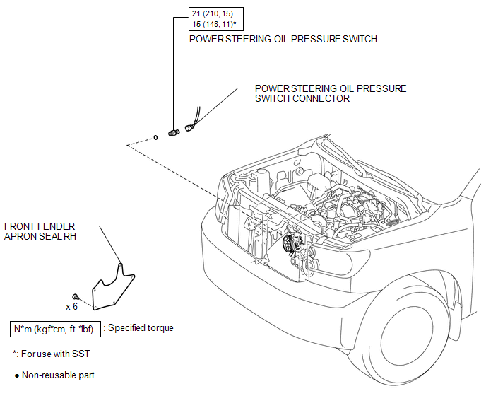 Installation INSTALLATION PROCEDURE 1. INSTALL POWER STEERING OIL PRESSURE SWITCH (a) Install a new O-ring to the power steering oil pressure switch. (b) Apply a light coat of engine oil to the O-ring of the power steering oil pressure switch. NOTICE:
(d) Connect the oil pressure switch connector. 2. INSTALL FAN AND GENERATOR V BELT (a) Install the fan and generator V belt (See page
3. ADD POWER STEERING FLUID 4. BLEED POWER STEERING FLUID 5. INSPECT FOR POWER STEERING FLUID LEAK 6. CHECK FLUID LEVEL 7. INSTALL FRONT FENDER APRON SEAL RH 8. INSTALL FRONT WHEEL
On-vehicle Inspection ON-VEHICLE INSPECTION PROCEDURE 1. INSPECT POWER STEERING OIL PRESSURE SWITCH (a) Check the oil pressure switch. (1) Connect the Techstream to the DLC3. (2) Turn the ignition switch to ON. (3) Turn the Techstream main switch on. (4) Enter the following menus: Powertrain / Engine and ECT / Data List / All Data / Power Steering pressure. (5) Start the engine. (6) Operate the steering wheel while idling, and read the value on the Techstream. Standard:
If not as specified, check for DTCs (See page Inspect the power steering system (See page
Removal REMOVAL PROCEDURE 1. REMOVE FAN AND GENERATOR V BELT (a) Remove the fan and generator V belt (See page
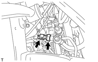
2. REMOVE FRONT WHEEL 3. REMOVE FRONT FENDER APRON SEAL RH 4. DRAIN POWER STEERING FLUID 5. REMOVE POWER STEERING OIL PRESSURE SWITCH
(b) Remove the power steering oil pressure switch. (c) Remove the O-ring. |
Toyota Tundra Service Manual > Sfi System: Fail-safe Chart
FAIL-SAFE CHART If any of the following DTCs are stored, the ECM enters fail-safe mode to allow the vehicle to be driven temporarily. DTC Component Fail-Safe Operation Fail-Safe Deactivation Condition P0011, P0021, P0015 and P0025 VVT system Idle up (Control of combustion worsening) Stopping fuel-cu ...


 ). If the power steering system inspection results are normal and a DTC
is not output, replace the power steering oil pressure switch.
). If the power steering system inspection results are normal and a DTC
is not output, replace the power steering oil pressure switch. ).
).