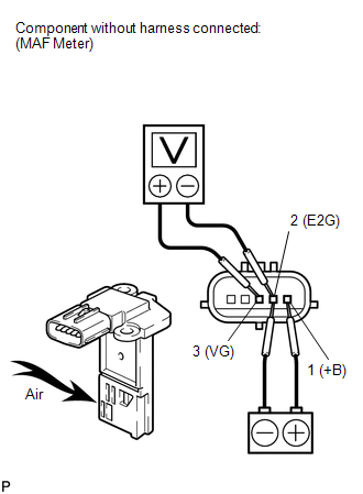
Components COMPONENTS ILLUSTRATION 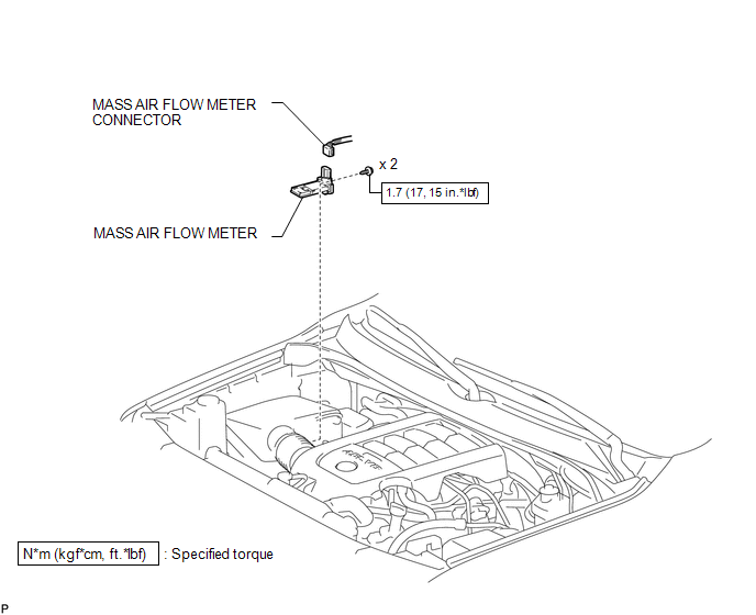 Inspection INSPECTION PROCEDURE 1. INSPECT MASS AIR FLOW METER (a) Check the output voltage.
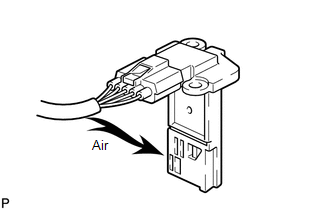
(2) Using a voltmeter, connect the positive (+) tester probe to terminal 3 (VG), and negative (-) tester probe to terminal 2 (E2G). (3) Blow air into the MAF meter, and check that the voltage fluctuates. If the result is not as specified, replace the MAF meter.
(c) Check the IAT sensor. 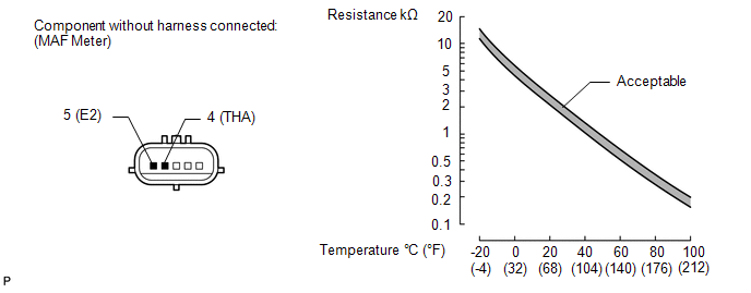
(1) Measure the resistance according to the value(s) in the table below. Standard Resistance:
If the result is not as specified, replace the MAF meter. Installation INSTALLATION CAUTION / NOTICE / HINT HINT: Perform "Inspection After Repairs" after replacing the mass air flow meter (See page
PROCEDURE 1. INSTALL MASS AIR FLOW METER HINT: Perform "Inspection After Repairs" after replacing the mass air flow meter (See page
(b) Connect the MAF connector. On-vehicle Inspection ON-VEHICLE INSPECTION PROCEDURE 1. CHECK MASS AIR FLOW METER (a) Check the mass air flow value. (1) Connect the Techstream to the DLC3. (2) Turn the ignition switch to ON. (3) Turn the Techstream main switch ON. (4) Enter the following menus: Powertrain / Engine / Data List / All Data / MAF.
Removal REMOVAL PROCEDURE 1. REMOVE MASS AIR FLOW METER 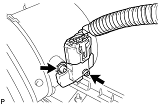 (a) Disconnect the MAF connector. (b) Remove the 2 screws and MAF meter. |
Toyota Tundra Owners Manual > Using the driving support
systems: Trailer brake controller
Summary of functions The trailer brakes can be controlled by the Trailer brake controller via the 7-pin connector. By selecting the type of brakes that are being used on the trailer (electric or electric-over-hydraulic) and setting the gain for the controller, the manual TRAILER BRAKE OUTPUT slider ...

 ).
).
 ), or wiring and ECM (See page